Comparative Study
. 1999 Jan;41(1):87-94.
doi: 10.1002/(sici)1522-2594(199901)41:1<87::aid-mrm13>3.0.co;2-x.

Referenceless interleaved echo-planar imaging

Affiliations
Comparative Study

Referenceless interleaved echo-planar imaging

S B Reeder et al. Magn Reson Med. 1999 Jan.

Abstract

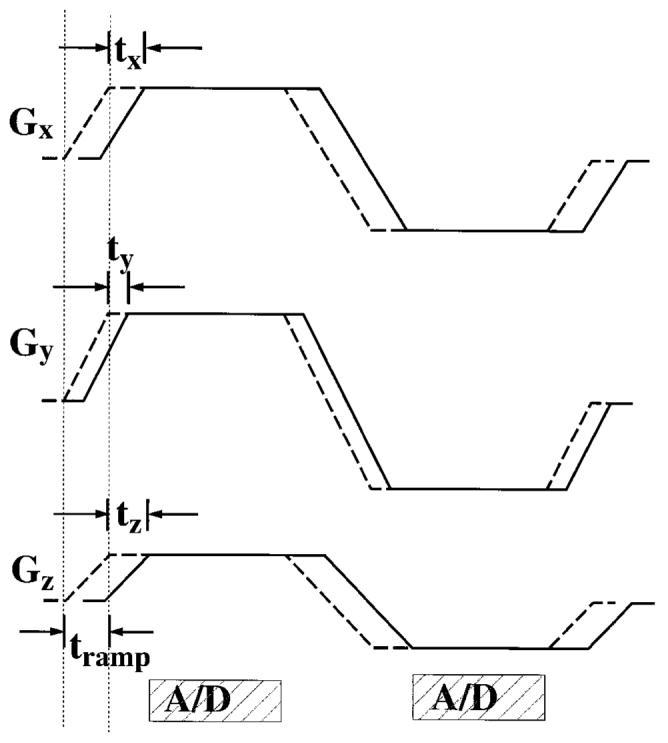
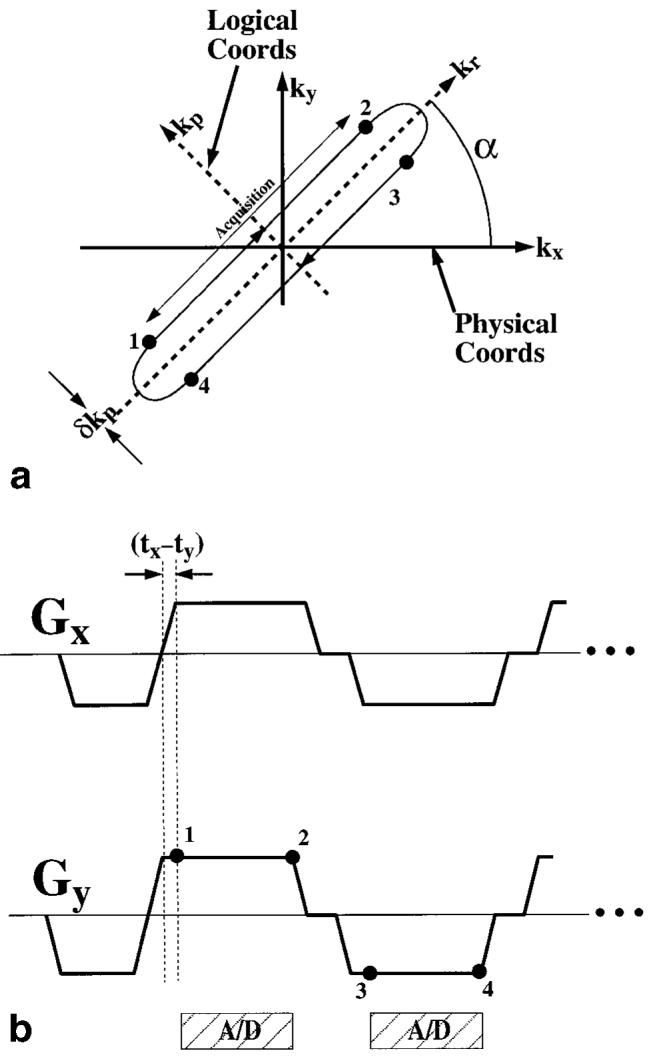
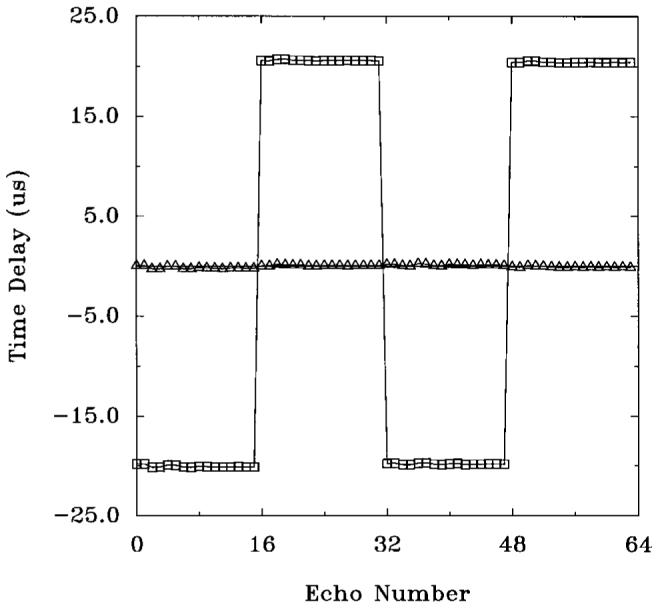
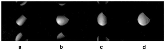
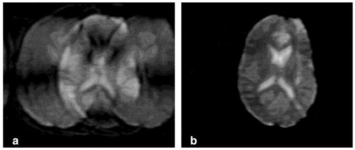
Interleaved echo-planar imaging (EPI) is an ultrafast imaging technique important for applications that require high time resolution or short total acquisition times. Unfortunately, EPI is prone to significant ghosting artifacts, resulting primarily from system time delays that cause data matrix misregistration. In this work, it is shown mathematically and experimentally that system time delays are orientation dependent, resulting from anisotropic physical gradient delays. This analysis characterizes the behavior of time delays in oblique coordinates, and a new ghosting artifact caused by anisotropic delays is described. "Compensation blips" are proposed for time delay correction. These blips are shown to remove the effects of anisotropic gradient delays, eliminating the need for repeated reference scans and postprocessing corrections. Examples of phantom and in vivo images are shown.


Figures

FIG. 1
FIG. 1
Readout gradient after oblique rotation played on the three physical gradient axes. The time delays of the physical gradients (tx, ty, tz), are shown, as well as the gradient ramp time (tramp). The sampling combs are also indicated (A/D).
FIG. 2
FIG. 2
(a) k-space trajectory after an in-plane rotation, for the physical gradient with anisotropic delays, shown in (b). The numbers in (b) correspond to the positions in k-space shown in (a). The sampling combs are also indicated (A/D). The shift in the readout direction is not depicted in these figures.
FIG. 3
FIG. 3
(a) Logical k-space trajectory for two echoes without phase encoding direction compensation blips (phase encoding blips off). (b) Compensated k-space trajectory using the sequence shown in (c). This removes the alternating shift (±δkp) resulting from anisotropic gradient delays. Numbers in (a) and (b) correspond to the position in k-space shown in (c). The area under the first blip is -δkp/γ and ±2δkp/γ for subsequent blips. Compensation blips are not drawn to scale.
FIG. 4
FIG. 4
(a) Logical k-space trajectory for two echoes without readout direction compensation blips. Misregistrations in the phase encoding direction (±δkp) have been ignored and a phase encoding blip has been played (not shown) to advance the position in k-space by Δkp. Asterisks (*) denote the position of echo within the data matrix. (b) Compensated k-space trajectory using the sequence shown in (c). This removes the alternating shift in the logical readout direction (±δkr) resulting from anisotropic gradient delays. Numbers in (b) correspond to the position in k-space also shown in (c). The area under the first blip is -δkr/γ and ±2δkr/γ for subsequent blips. Compensation blips are not drawn to scale.
FIG. 5
FIG. 5
Time delays measured for reference scans at different orientations, rotated in the X-Y, X-Z, and Y-Z planes. Symbols represent measured data, and solid lines are curves fit to Eq. [10]. The fit values for the three times delays were: tx = 19.7 μs, ty = 16.8 μs, and tz = 14.2 μs.
FIG. 6
FIG. 6
Time delays (μs) plotted against phase encoding index for a four-echo train length EPI data set before and after compensation blip correction. Accurate correction of the delay is seen.
FIG. 7
FIG. 7
Axial single shot images of a water phantom, after 45° in-plane rotation, (a) without any compensation, (b) with compensation in the logical readout direction only, (c) in the logical phase encoding direction only, and (d) compensation in both directions. Other imaging parameters include: 128 × 128 matrix, 90° flip angle, 32-cm FOV, 8-mm slice thickness, and ±64 kHz. Phase encoding is in the vertical direction.
FIG. 8
FIG. 8
Two-shot axial echo-planar image of a brain, (a) before, and (b) after compensation blip correction. Other imaging parameters include: 160 × 80 matrix, 90° flip angle, 28-cm FOV, 8-mm slice thickness, and chemical presaturation was used to reduce fat artifacts. Phase encoding is in the horizontal direction.
FIG. 9
FIG. 9
Phase encoding shifts in the oblique EPI data matrix resulting from anisotropic gradient time delays. The shift δkp, as well as the separation between lines of k-space, Δkp are indicated. In this example, ni = 4 and Np = 16, and arrows indicate even and odd echoes.

References

    1. Mansfield P. Multi-planar image formation using NMR spin-echoes. J Phys C. 1977;10:L55–L58.
    1. Kwong KK. Functional magnetic resonance imaging with echo planar imaging. Magn Reson Q. 1995;11:1–20. - PubMed
    1. Turner R, LeBihan D. Single-shot diffusion imaging at 2.0 Tesla. J Magn Reson Imaging. 1990;86:445–452.
    1. Moseley ME, Sevick R, Wendland MF, White DL, Mintorovitch J, Asgari HS, Kucharczyk J. Ultrafast magnetic resonance imaging: diffusion and perfusion. Can Assoc Radiol J. 1991;42:31–38. - PubMed
    1. Stehling MK, Turner R, Mansfield P. Echo-planar imaging: magnetic resonance imaging in a fraction of a second. Science. 1991;254:43–50. - PubMed

Publication types

LinkOut - more resources