

A repetitive mode of activation of discrete Ca2+ release events (Ca2+ sparks) in frog skeletal muscle fibres
- PMID: 10050007
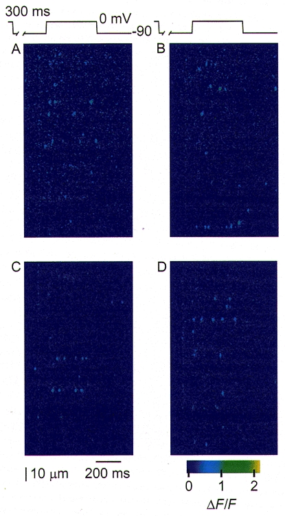
- PMCID: PMC2269172
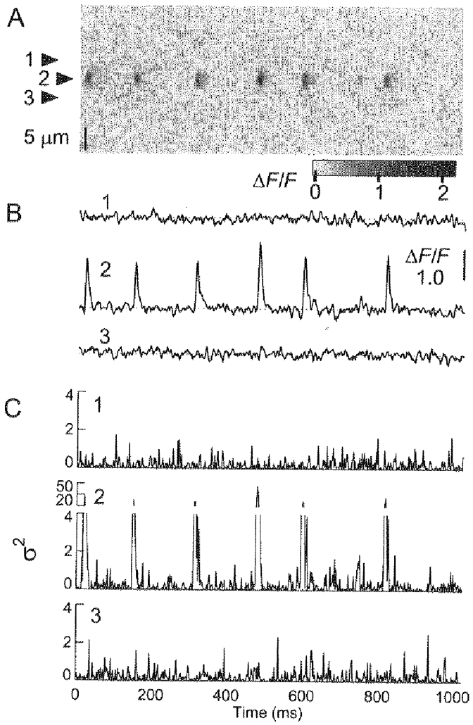
- DOI: 10.1111/j.1469-7793.1999.391ac.x
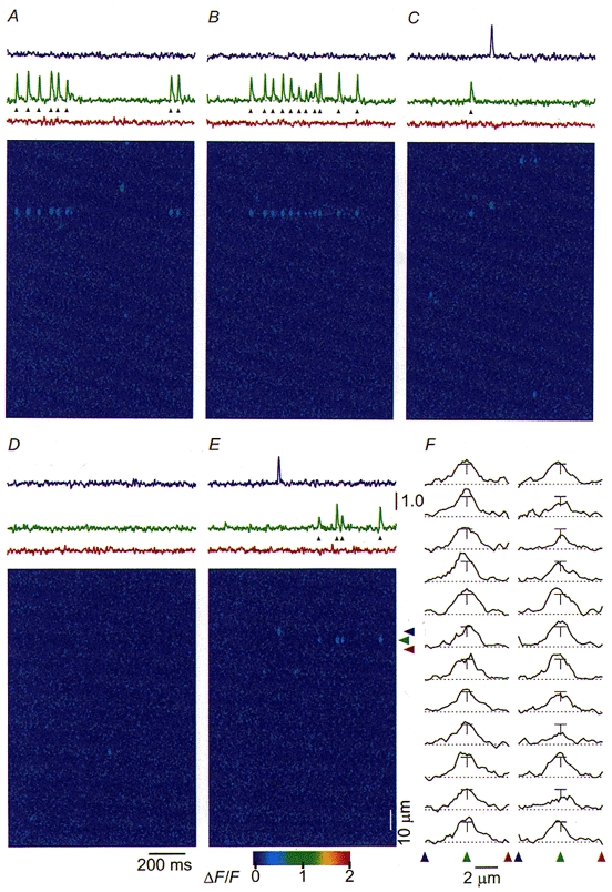
A repetitive mode of activation of discrete Ca2+ release events (Ca2+ sparks) in frog skeletal muscle fibres
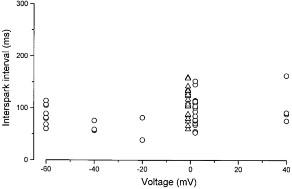
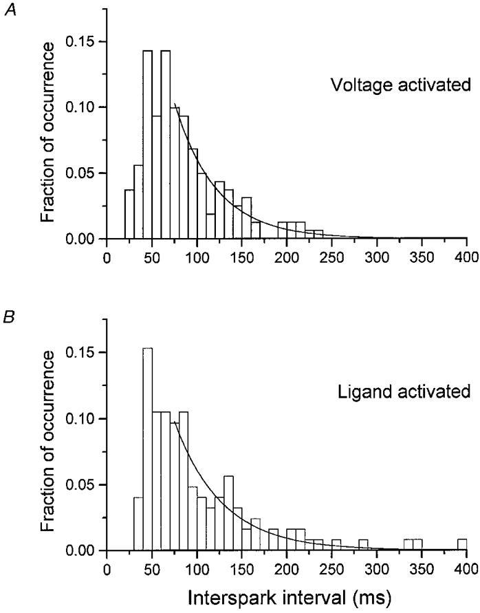
Abstract
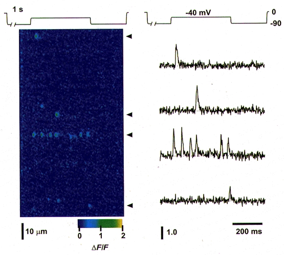
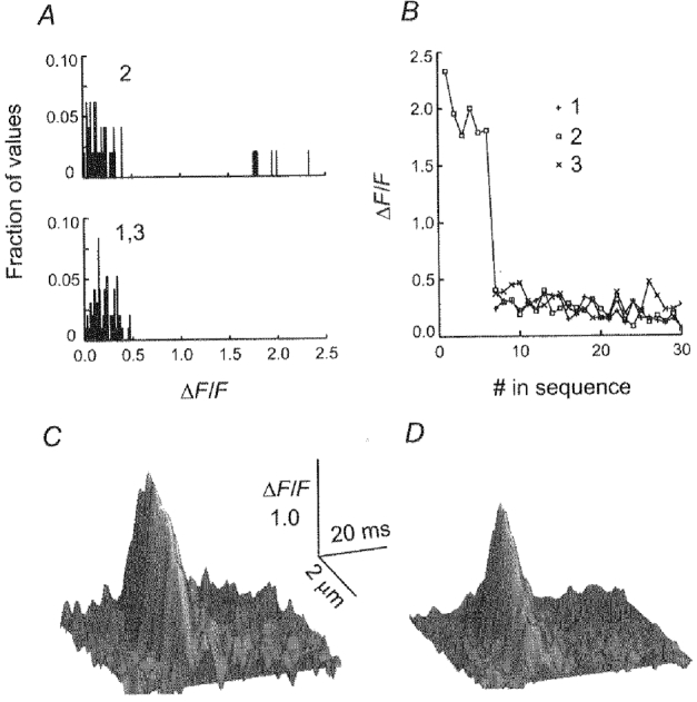
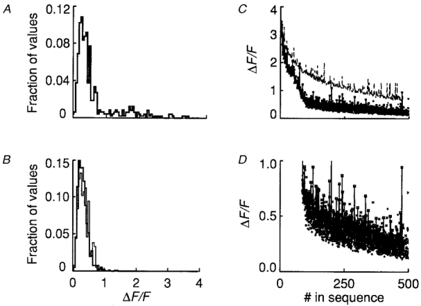
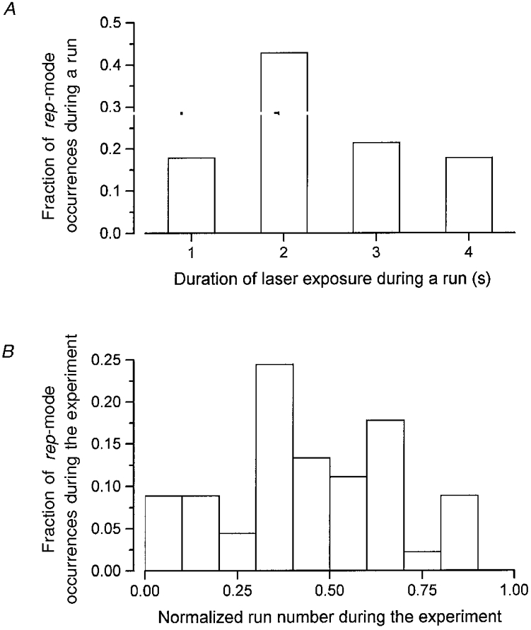
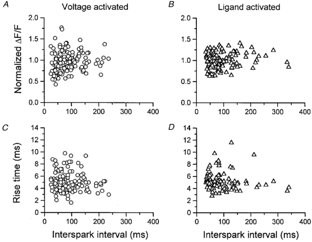
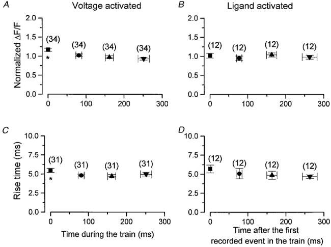
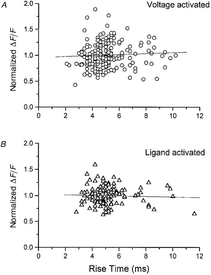
1. Ca2+ release events (Ca2+ 'sparks'), which are believed to arise from the opening of a sarcoplasmic reticulum (SR) Ca2+ release channel or a small cluster of such channels that act as a release unit, have been measured in single, frog (Rana pipiens) skeletal muscle fibres. 2. Under conditions of extremely low rates of occurrence of Ca2+ sparks we observed, within individual identified triads, repetitive Ca2+ release events which occurred at a frequency more than 100-fold greater than the prevailing average event rate. Repetitive sparks were recorded during voltage-clamp test depolarizations after a brief (0.3-2 s) repriming interval in fibres held at 0 mV and in chronically depolarized, 'notched' fibres. 3. These repetitive events are likely to arise from the re-opening of the same SR Ca2+ release channel or release unit operating in a repetitive gating mode ('rep-mode'), rather than from the random activation of multiple, independent channels or release units within a triad. A train of rep-mode events thus represents a series of Ca2+ sparks arising from a single location within the fibre. Rep-mode events are activated among different triads in a random manner after brief repriming. The frequency of repetitive events among all identified events during voltage-clamp depolarization to 0 mV after brief repriming was 3.9 +/- 1.3 %. The occurrence of repetitive events was not related to exposure of the fibre to laser illumination. 4. The events observed within a rep-mode train exhibited a relatively uniform amplitude. Analysis of intervals between identified events in triads exhibiting rep-mode trains indicated similar variations of fluorescence as in neighbouring, quiescent triads, suggesting there was not a significant number of small, unidentified events at the triads exhibiting rep-mode activity. 5. The distribution of rep-mode interspark intervals exhibited a paucity of events at short intervals, consistent with the need for recovery from inactivation before activation of the next event in a repetitive train. The mean interspark interval of repetitive sparks during voltage-clamp depolarizations was 88 +/- 5 ms, and was independent of membrane potential. 6. The individual Ca2+ sparks within a rep-mode train were similar in average amplitude and spatiotemporal extent to singly occurring sparks, suggesting a common mechanism for termination of the channel opening(s) underlying both types of events. The average properties of the sparks did not vary during a train. The relative amplitude of a spark within a rep-mode was not correlated with its rise time. 7. Repetitive Ca2+ release events represent a mode of gating of SR Ca2+ release channels which may be significant during long depolarizations and which may be influenced by the biochemical state of the SR ryanodine receptor Ca2+ release channels.
Figures
References
-
- Armisen R, Sierralta J, Velez P, Naranjo D, Suarez-Isla BA. Modal gating in neuronal and skeletal muscle. American Journal of Physiology. 1996;271:C144–153. - PubMed
-
- Blatter LA, Tsugorka A, Shirokova N, Rios E. Eager triads in skeletal muscle: Heterogeneous distribution of voltage-elicited Ca2+ release revealed by confocal microscopy. Biophysical Journal. 1996;70:A235. Abstract.
-
- Colquhoun D, Hawkes AG. On the stochastic properties of bursts of single ion channel openings and of clusters of bursts. Philosophical Transactions of the Royal Society B. 1982;300:1–59. - PubMed
Publication types
MeSH terms
Substances
Grants and funding
LinkOut - more resources
Full Text Sources
Research Materials
Miscellaneous