. 1999 Jul;114(1):1-12.
doi: 10.1085/jgp.114.1.1.

Elimination of the slow gating of ClC-0 chloride channel by a point mutation

Affiliations

Elimination of the slow gating of ClC-0 chloride channel by a point mutation

Y W Lin et al. J Gen Physiol. 1999 Jul.

Abstract

The inactivation of the ClC-0 chloride channel is very temperature sensitive and is greatly facilitated by the binding of a zinc ion (Zn2+) from the extracellular side, leading to a Zn2+-induced current inhibition. To further explore the relation of Zn2+ inhibition and the ClC-0 inactivation, we mutated all 12 cysteine amino acids in the channel and assayed the effect of Zn2+ on these mutants. With this approach, we found that C212 appears to be important for the sensitivity of the Zn2+ inhibition. Upon mutating C212 to serine or alanine, the inactivation of the channel in macroscopic current recordings disappears and the channel does not show detectable inactivation events at the single-channel level. At the same time, the channel's sensitivity to Zn2+ inhibition is also greatly reduced. The other two cysteine mutants, C213G and C480S, as well as a previously identified mutant, S123T, also affect the inactivation of the channel to some degree, but the temperature-dependent inactivation process is still present, likewise the high sensitivity of the Zn2+ inhibition. These results further support the assertion that the inhibition of Zn2+ on ClC-0 is indeed due to an effect on the inactivation of the channel. The absence of inactivation in C212S mutants may provide a better defined system to study the fast gating and the ion permeation of ClC-0.


Figures
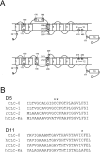
Figure 1
Figure 1
(A) Positions of cysteine residues of ClC-0. The membrane topology of the top panel was drawn according to Schmidt-Rose and Jentsch 1997, whereas the bottom panel was drawn according to Fahlke et al. 1997. Placing the D8–D9 linker in intracellular side (bottom), however, violates the fact that there is a glycosylation site in this linker (Middleton et al. 1994). (B) Alignment of the amino acid sequences of D5 and D11 from several ClC channels. Stars on top of the sequences denote C212, C213 (in D5), and C480 (in D11) of ClC-0.
Figure 3
Figure 3
Sensitivity of wild-type ClC-0 and cysteine mutants to extracellular Zn2+ inhibition. (A) Inhibition by 10 μM extracellular Zn2+ on the steady state current of the wild-type channel (WT), C212S, C213G, and C480S. Down- and upward arrows indicate the application and washout of 10 μM Zn2+, respectively. Dotted lines represent zero-current level. (B) Dose-dependent inhibition of Zn2+ for the four channels shown in A. All data points were the average of 3–11 determinations. The current amplitude was normalized to the value right before the application of Zn2+. Solid curves were drawn according to a Langmuir function: formula image, with values of K 1/2 and I : (wild type) 1.0 μM and 0.87; (C212S) 47.5 μM and 0.33; (C213G) 3.5 μM and 0.78; (C480S) 9.3 μM and 0.88.
Figure 5
Figure 5
Temperature dependence of the macroscopic current of C212S. (A) Temperature-jump experiments showing different degrees of the increase in the steady state current. All current amplitudes are normalized to the value of the first point and the dotted lines are the zero-current level. All data points were from the average of four measurements. (B) Temperature-dependent increase of the whole oocyte current. I1 was measured right before the increase of the temperature, whereas I2 was measured near the end of the temperature jump. The solid line is the best fit to a linear equation formula image, with a fitted formula image. Data points were from the average of four to six measurements.
Figure 2
Figure 2
Quasi–steady state activation curves of the slow gate. (A) Wild-type (WT) ClC-0; temperature: 23.7–23.8°C formula image. (B) C212S; temperature: 25.9–27.1°C formula image. (C) C213G; temperature: 20.1–21.1°C formula image. (D) C480S; temperature: 21.5–22.1°C formula image The solid line connecting the adjacent points is a straight line. Insets are the steady state P o–V curve of the fast gate formula image.
Figure 4
Figure 4
Temperature dependence of macroscopic current. The temperatures T1 and T2 were (°C): (A) Wild-type ClC-0, 22.0 and 28.7 formula image. (B) C212S, 22.0 and 28.8 formula image. (C) C213G, 20.7 and 30.0 formula image. (D) C480S, 22.3 and 28.5 formula image. All current values were normalized to the amplitude of the first data point and the dotted lines represent the zero-current level.
Figure 7
Figure 7
(A and B) Single-channel recordings of C212S and C212A. Continuous recording for 5 min in each case at a holding potential of −50 mV. The top of each panel is in a compressed time window. a–d are the recordings starting at the indicated points (arrows) with an expanded time window. The scale bars for the compressed and expanded time windows in A also apply to B. No inactivation event was discernible in both A and B throughout the whole recordings. Temperature was ∼23–24°C. (C) Comparison of cumulative dwell-time distributions of the events at conductance levels D (□), M (•), and U (▴) between wild-type ClC-0 (left) and C212S (right). The recording trace of the wild-type channel used for analysis is the same as the 4-min trace in Fig. 6 A. For C212S, the analyzed trace is the first 4-min recording shown in A. All events in each of the three levels were used for analysis. The numbers of events in levels D, M, and U are: (wild type) 1,399, 7,009, and 5,612; and (C212S) 1,731, 7,822, and 6,092, respectively.
Figure 6
Figure 6
Single-channel recordings of (A) Wild-type ClC-0, (B) C213G, and (C) C480S. Continuous recording from excised inside-out patch at a holding potential of −50 mV. The top of each panel shows a 4-min recording in a compressed time window. The bottom is with an expanded time window starting at the position indicated by the arrow. Note that two C213G channels were present in the patch. The temperature during recording was ∼23–25°C.
Figure 8
Figure 8
Binomial distribution of the three current levels in C212S. (A) Continuous 6-min single-channel recording trace at various membrane voltages. Same channel as the one shown in Fig. 7 A. The recording at −50 mV corresponds to the first ∼100-s recording in Fig. 7 A. (B) Representative 2-s recording traces starting at the positions indicated by arrows in A. (C) Open probability of the fast gate (P o) and the probabilities of the three current levels, f D, f M, and f U, at membrane potentials from −90 (top) to −50 (bottom) mV. The analysis was made on the corresponding regions shown in A, with the length of each segment being: 44 s (−90 mV), 62 s (−80 mV), 70 s (−70 mV), 72 s (−60 mV), and 106 s (−50 mV). The measured state probabilities, f D, f M, and f U, are represented by bars, whereas ○'s denote f 0, f 1, and f 2, the predicted values of state probabilities calculated from P o.
Figure 9
Figure 9
Comparison of single-channel properties of wild-type ClC-0 and C212S. The parameters of the fast gate were calculated from and the single-channel current amplitudes were measured from all-points amplitude histograms. (A) Steady state voltage dependence of the open probability of the fast gate. (B) Opening rate constants of the fast gate as a function of membrane potential. (C) Closing rate constants of the fast gate. (D) Single-channel I–V curves. ○ and ▴ are the current amplitudes of one-pore opening, whereas □ and ▾ are those of two-pore openings. In all panels, solid symbols represent wild-type ClC-0, whereas open symbols are C212S.
Figure 10
Figure 10
Probing the slow gate of S123T. (A) Quasi–steady state activation curve off the slow gate. (B) Temperature dependence of the macroscopic current from the whole oocyte. (C) Dose-dependent inhibition of the channel by extracellular Zn2+. The solid curve is drawn according to the Langmuir function described in Fig. 3, with K 1/2 and I: 1.72 μM and 0.85 formula image.

Similar articles

Cited by

References

    1. Backx P.H., Yue D.T., Lawrence J.H., Marban E., Tomaselli G.F. Molecular localization of an ion-binding site within the pore of mammalian sodium channels. Science. 1992;257:248–251. - PubMed
    1. Chen T.-Y. Extracellular zinc ion inhibits ClC-0 chloride channels by facilitating slow gating. J. Gen. Physiol. 1998;112:715–726. - PMC - PubMed
    1. Chen T.-Y., Miller C. Nonequilibrium gating and voltage dependence of the ClC-0 Cl− channel. J. Gen. Physiol. 1996;108:237–250. - PMC - PubMed
    1. Fahlke Ch., Yu H.T., Beck C.L., Rhodes T.H., George A.L., Jr. Pore-forming segments in voltage-gated chloride channels. Nature. 1997;390:529–532. - PubMed
    1. Fersht, A. 1985. The structures and mechanisms of selected enzymes. In Enzyme Structure and Mechanism, 2nd ed. W.H. Freeman and Co., New York. 389–452.

Publication types

Substances