Review
. 1999 Dec;63(4):751-813, table of contents.
doi: 10.1128/MMBR.63.4.751-813.1999.

Recombinational repair of DNA damage in Escherichia coli and bacteriophage lambda

Affiliations
Review

Recombinational repair of DNA damage in Escherichia coli and bacteriophage lambda

A Kuzminov. Microbiol Mol Biol Rev. 1999 Dec.

Abstract

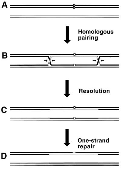
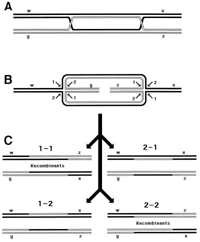
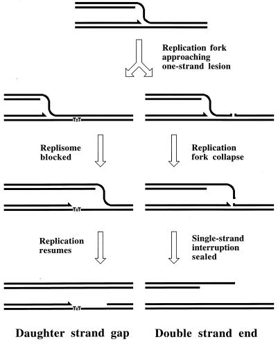
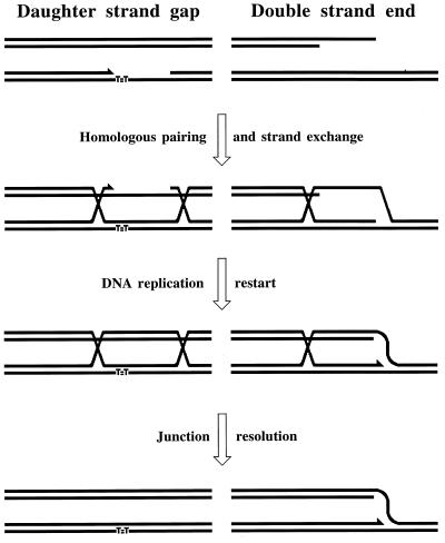
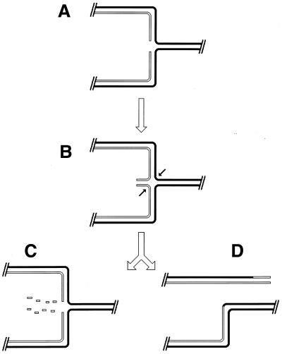
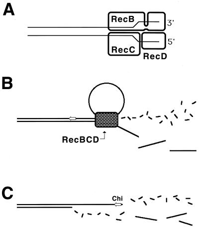
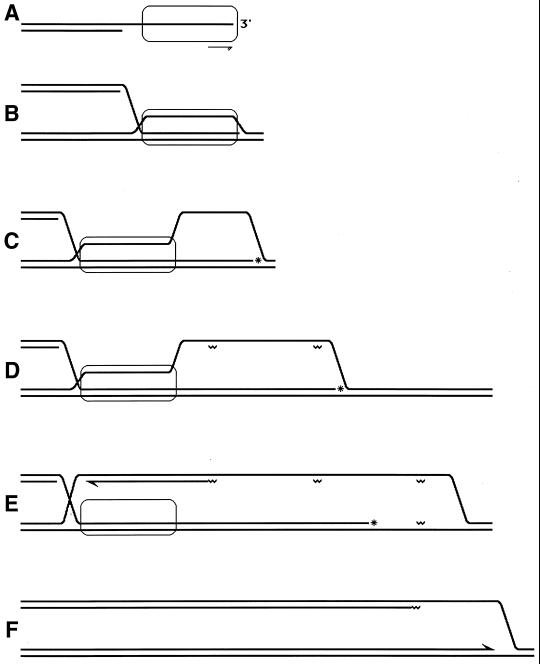
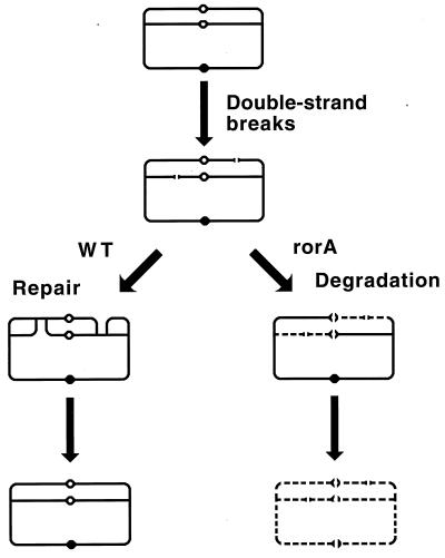
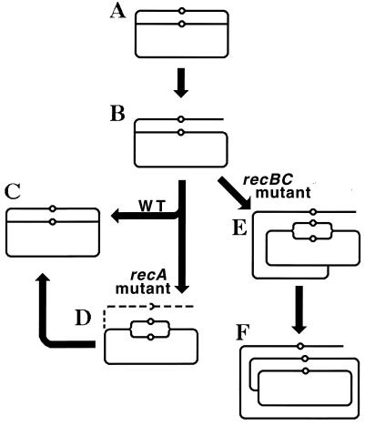
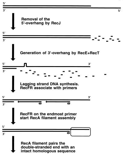
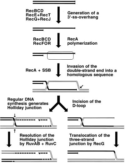
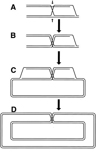
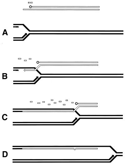
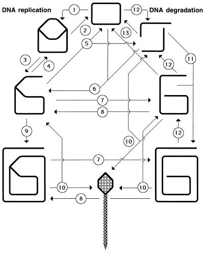
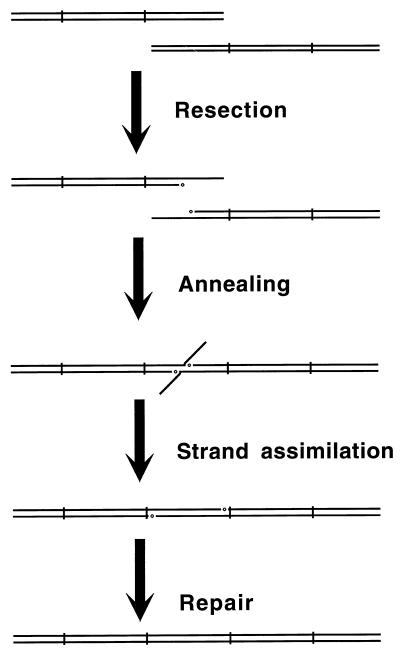
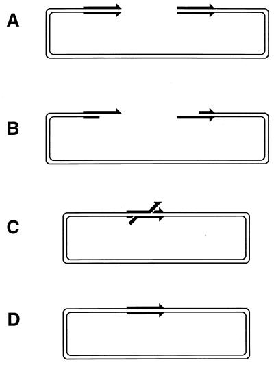
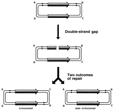
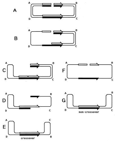
Although homologous recombination and DNA repair phenomena in bacteria were initially extensively studied without regard to any relationship between the two, it is now appreciated that DNA repair and homologous recombination are related through DNA replication. In Escherichia coli, two-strand DNA damage, generated mostly during replication on a template DNA containing one-strand damage, is repaired by recombination with a homologous intact duplex, usually the sister chromosome. The two major types of two-strand DNA lesions are channeled into two distinct pathways of recombinational repair: daughter-strand gaps are closed by the RecF pathway, while disintegrated replication forks are reestablished by the RecBCD pathway. The phage lambda recombination system is simpler in that its major reaction is to link two double-stranded DNA ends by using overlapping homologous sequences. The remarkable progress in understanding the mechanisms of recombinational repair in E. coli over the last decade is due to the in vitro characterization of the activities of individual recombination proteins. Putting our knowledge about recombinational repair in the broader context of DNA replication will guide future experimentation.


Figures

FIG. 1
FIG. 1
The idea of two-strand repair. (A) A DNA molecule with a two-strand lesion (small open rectangles in the solid duplex) is shown side-by-side with an intact homolog (open duplex). (B) The two sequences have exchanged strands in a homologous region, converting the two-strand lesion into a pair of one-strand lesions. (C) Junction resolution (the strands to cut are shown in panel B) separates the chromosomes from each other. (D) Excision repair removes the one-strand lesions, completing the overall repair reaction. Note that if black and white “parental” DNAs are not identical, the resulting chromosomes may become “recombinant.”
FIG. 2
FIG. 2
The four ways to resolve a joint molecule with a double junction. Lowercase letters w, x, y, and z designate unique sites which serve as markers on the homologous chromosomes. A junction is resolved by two symmetrical single-strand cuts (small black arrows in panel B) across each other. Each such diagonal pair of cuts is numbered either 1 or 2 for each junction. If junctions freely isomerize and are resolved independently of each other, four outcomes of the resolution are expected. In two of the outcomes, the chromosome arms will be exchanged, resulting in recombinant chromosomes. (A) A joint molecule with two junctions as shown in Fig. 1B. (B) The same joint molecule isomerized to show both junctions in the open planar configuration (498). (C) The four resolution outcomes, numbered according to the resolution options realized at the left and the right junctions.
FIG. 3
FIG. 3
The two major types of replication-induced two-strand lesions. A replication fork moves from left to right along the template DNA with unrepaired one-strand lesions. The left template contains a noncoding lesion (T=T, thymine dimer), the right template has a single-strand interruption. Additional explanations are given in the figure and in the text.
FIG. 4
FIG. 4
The two pathways of recombinational repair in E. coli. On the left, the RecF (daughter strand gap repair) pathway is shown; on the right, the RecBC (double-strand end repair) pathway is shown. Additional explanations are given in the text.
FIG. 5
FIG. 5
An idealized induction kinetics of the four groups of LexA-controlled genes (also, see reference 611). The graph illustrates the well-regulated nature of the SOS response. Both the x axis (time) and y axis (the level of the SOS induction) are in arbitrary units; therefore, the heights of the three curves are not to be compared.
FIG. 6
FIG. 6
RecA filament in vitro: photographs and molecular model. (A) A relaxed circular duplex DNA completely covered by RecA filament. Naked duplex DNA of the same length, lying mostly inside the RecA filament, illustrates that DNA within RecA filament is stretched 1.5 times. Reprinted from reference with permission of the publisher. (B) A RecA-covered circular ssDNA molecule; the arrow points to a segment complexed by SSB. Below, another ssDNA circle of the same length can be seen, but since it is entirely complexed with SSB, it appears very different, i.e., much smaller and kinky. Note that while RecA filament stretches ssDNA, SSB compacts it. Reprinted from reference with permission of the publisher. (C) A crystal structure-based molecular model of an 18-monomer segment of RecA filament with three symmetry-related monomers in gray. Each of these monomers is enlarged on the right to show residues conserved among eubacterial RecA proteins (see reference for details). In such a filament, the 5′ end of DNA1 would be at the top. Reprinted from reference with permission of the publisher.
FIG. 7
FIG. 7
The distinguishable phases of RecA-promoted reactions, as they are thought to happen in vivo. Black lines indicate a damaged duplex; white lines indicate an intact duplex; the open rectangle with rounded corners indicates a RecA filament; the irregularity in one of the black DNA strands indicates a noncoding lesion. The left side represents daughter strand gap repair; the right side represents double-strand end repair. Explanations are given in the figure.
FIG. 8
FIG. 8
SSB helps in the assembly of the functional RecA filament. The thick line indicates ssDNA; stem-loop structures indicate secondary (duplex) structures in ssDNA at physiological Mg2+ concentrations; open rectangles with rounded corners indicate RecA filaments; quartets of small circles indicate SSB tetramers. Without SSB (the top and the left side), formation of long contiguous RecA filaments on ssDNA is compromised because the growth of nascent filaments is impossible past the secondary structures. SSB helps RecA to polymerize into long contiguous filaments (the right side and the bottom) by ironing out secondary structures in the ssDNA.
FIG. 9
FIG. 9
The three ways to remove a double DNA junction. A pair of four-strand junctions is shown, but the same applies to a pair of three-strand junctions or to a combination of one four-strand junction and one three-strand junction. The two DNA duplexes participating in the joint molecule are shown as either solid or open double lines. Small arrows near the junctions indicate the direction of junction translocation. Scissors mark the position of strand cuts. (A) Removal by translocation only (topoisomerase model). (B) Removal by symmetrical single-strand cuts only (resolution). (C) Removal by a combination of cuts and translocation. Additional explanations are given in the text.
FIG. 10
FIG. 10
Removal of a single DNA junction. A three-strand junction is shown, but the same applies to a four-strand junction. The two DNA duplexes participating in the joint molecule are shown as either solid or open double lines. Small arrows near the junctions indicate the direction of junction translocation. Scissors mark the position of strand cuts. (A) Removal by translocation only. (B) Removal by symmetric single-strand cuts only. Note that for the three-strand junction, the black strand already has an end across the cut in the white strand. (C) Removal by a combination of a cut and translocation. Additional explanations are given in the text. The last two options create a replication fork framework, whereas the first option seems to be nonproductive. However, if the original two-strand lesion was a double-strand break and the invading end has already been extended by DNA synthesis, the expelled extended end can now anneal with the other end of the break, permitting lesion repair (517).
FIG. 11
FIG. 11
Interactions of RuvA, RuvB, and RuvC with Holliday junctions. The two homologous duplexes (solid and open double lines) are connected by a single Holliday junction. RuvA tetramer is shown as the four-petal flower, RuvB hexameric rings are shown as the trapezoid washers on DNA duplexes, RuvC dimer (E) is shown as the pair of open circles. The direction of DNA movement through RuvAB complex in panels D and E is indicated by arrows. (A) A Holliday junction in a folded conformation, observed in vitro under conditions mimicking physiological ones. (B) A RuvA tetramer binds the junction to open it into a square planar conformation, while two RuvB hexamers bind two opposite arms of the junction. (C) The RuvAB translocase: the same as in panel B, but the second RuvA tetramer binds to the unoccupied side of the junction, locking it in a turtle shell configuration. (D) One of the RuvA tetramers is removed to show junction isomerization, promoted by the pulling action of RuvB (compare with panel B). (E) RuvABC resolvasome: one of the RuvA tetramers has left to allow a RuvC dimer to assume a position for the junction resolution. The resolution sites (diamonds in the opposite DNA strands) are drawn into the junction by the action of RuvB. (F) RuvC cleavage at the resolution sites separates the interacting homologs. The RuvABC resolvasome is not shown.
FIG. 12
FIG. 12
The “flip” and “flop” sides of a Holliday junction in the open conformation. The same junction is shown from the opposite sides. The 3′ and 5′ ends of DNA strands are marked. In the center, the 5′-to-3′ direction around the junctions is indicated by arrows. RuvC binds to the “clockwise” side of the junction, whereas RuvA binds to the “counterclockwise” side.
FIG. 13
FIG. 13
Hypothetical removal of a single three-strand junction by RecG. RecA filament is shown as an open rectangle with rounded corners; RecA monomers (in panel C) are shown as open circles; RecG is shown as a dotted oval. The small arrow in panel A indicates the position of the required single-strand incision. Explanations are given in the text.
FIG. 14
FIG. 14
Experimentally established principles of the daughter strand gap repair in E. coli. Solid lines indicate parental DNA strands; open lines indicate newly synthesized daughter DNA strands; diamonds indicate thymine dimers; small horizontal arrows indicate single-strand scissions required to resolve the joint molecules. (A) A DNA molecule containing unrepaired noncoding lesions (for example, thymine dimers). (B) Replication of this molecule generates two molecules with single-strand gaps in the daughter strands opposite the lesions (538). Eventually, these gaps are repaired in a RecA-dependent way (606). (C to H) Experiments by Rupp et al. (539) had revealed that after gap closure, the newly synthesized strands are connected with the parental strands (strand exchange), suggesting a model for recombinational repair of daughter-strand gaps (C to E). Later, Ley (357) found that the gaps are transferred from the daughter strands to the parental strands, while Ganesan (199) found that the thymine dimers are transferred in the opposite direction, from the parental strands to the daughter strands, suggesting the formation and resolution of Holliday junctions (F to H).
FIG. 15
FIG. 15
Overview of daughter strand gap repair. (A) A DNA molecule with a daughter-strand gap. T=T, the thymine dimer that caused the gap. (B) Synapsis of the gapped molecule with the intact homologous DNA. (C) Filling in of the gap and repair of the lesion that caused the gap. (D) Disengagement of the two DNA molecules. The RuvC cleavages are indicated by small vertical arrows in panel C. Additional explanations are given in the text and in the figure.
FIG. 16
FIG. 16
Presynaptic phase of the daughter-strand gap repair: RecA filament assembly and replisome reactivation. The replisome is depicted as a big open oval, and its DnaN subunit (the clamp) is indicated as a smaller open rectangle with rounded corners. The 3′ end of the nascent DNA is stalled at the noncoding lesion (the irregularity in the lower strand). SSB is shown as quartets of open circles around single-stranded region; RecFR (small black rectangles) are associated with the RNA primer (wavy segment in the upper strand at the very right). The RecA filament is shown as a hatched rectangle with rounded corners spreading to the left. Explanations are given in the figure and in the text.
FIG. 17
FIG. 17
Topoisomerase requirements during synapsis. Regular DNA superhelicity is shown in the top and bottom double helices. In the two middle panels, the helices are either overwound (too much coiling) or underwound (missing coils). DNA gyrase removes extra coils from the original (black-black) duplex, while DNA Topo I (TopA) introduces the missing coils in the hybrid (black-white) duplex.
FIG. 18
FIG. 18
Synaptic and postsynaptic phases of daughter strand gap repair. This figure is a sequel to Fig. 16. The RecA filament is shown as a hatched rectangle with rounded corners. From top to bottom, the stages are pairing with an intact homolog, repair of the gap, and removal of the DNA junctions and the associated RecA filament. Explanations are given in the figure and in the text.
FIG. 19
FIG. 19
Model for the translesion DNA synthesis. This figure is a sequel to Fig. 16 and shows an alternative to the mechanism illustrated in Fig. 18. The RecA filament is shown as a hatched rectangle; the DnaN clamp is shown as a small open rectangle; UmuC is shown as a small black rectangle associated with the DnaN clamp; UmuD is shown as small black dimer circles, some of them associated with UmuC; the replisome is shown as an open oval. Explanations are given in the figure and in the text.
FIG. 20
FIG. 20
Replication-dependent origin of double-strand ends. (A) Replication fork collapse at a single-strand interruption in template DNA. The replisome is shown as the square group of circles, speeding from left to right along the DNA while replicating it. (B) Preexisting interruptions in the same DNA strand at both replication forks of a replication bubble cause chromosome fragmentation.
FIG. 21
FIG. 21
Replication fork reversal as the mechanism of replication fork breakage. A replication fork is shown moving from left to right; solid lines indicate parental strands; open lines indicate newly synthesized strands. (A) The progress of the replication fork is blocked (replisome mulfunctioning, a protein bound to DNA). (B) This results in replication fork reversal to generate a double-strand end, composed of the newly synthesized DNA strands, and a Holliday junction. (C) ExoV-catalyzed degradation of the double-strand end eliminates the Holliday junction. (D) Alternatively, resolution of the Holliday junction by RuvABC (small arrows in panel B) breaks the replication fork.
FIG. 22
FIG. 22
Mode of RecBCD enzyme binding to a DNA end and patterns of RecBCD-promoted DNA hydrolysis. The direction of travel of the enzyme through the DNA duplex is from right to left. (A) Scheme of RecBCD binding to a double-strand end. The C-terminal domain of RecB, containing the nuclease active site, is shown as a separate subdomain. The final 5 to 6 bp of the duplex end are unwound. (B) Mode of the RecBCD action before it has seen a Chi. The top strand ends 3′ at the right. (C) Mode of RecBCD action after the enzyme has seen a Chi. The enzyme itself is not shown.
FIG. 23
FIG. 23
Overview of double-strand end repair. RecA filament is shown as an open rectangle with rounded corners. Small one-sided arrow indicates the direction of RecA filament assembly. The star indicates limited DNA synthesis by DNA pol I; little wavy segments indicate RNA primers. (A) RecA polymerizes on a 3′ single-stranded overhang, generated by the RecBCD action after Chi. (B) RecA-catalyzed invasion of the 3′ end allows limited DNA synthesis to be primed by DNA pol I. (C) As a result of this synthesis, a primosome assembly structure is created in the displaced strand. (D) PriA assembles a primosome at the displaced strand, which then lays down primers and unwinds DNA at the fork. (E) A replisome is loaded onto the primed replication fork; the three-strand junction is being converted into a Holliday junction. (F) Double-strand end repair is completed by resolution of the Holliday junction.
FIG. 24
FIG. 24
Lethality caused by double-strand breaks in the replicated portion of the genome in rorA mutants. The chromosome is depicted as a theta-replicating structure, with the single line representing duplex DNA. The origin of DNA replication is denoted by small open circles at the top of the chromosome; the terminus is shown as a solid circle at the bottom. If both daughter branches of a replicating chromosome are broken at positions close to each other, the double-strand breaks have more chances of being repaired in the WT cells than in rorA mutant cells, due to the increased DNA degradation in the latter.
FIG. 25
FIG. 25
Outline of the maintenance of circular chromosome. The chromosome is shown as a rectangle with rounded corners (the single line represents duplex DNA). The origin of DNA replication is denoted by small open circles at the top of the chromosome. (A and B) A theta-replicating chromosome (A) may suffer a collapse of one of the replication forks, becoming a sigma-replicating chromosome (B). (C) In a wild-type strain, the double-strand end is then degraded by RecBCD and reattached to the circular domain with the help of RecA. (D) In the absence of RecA, the linear replicating branch is completely degraded by RecBCD, while a new round of theta replication is initiated from the origin. (E and F) In the absence of RecBCD, the chromosome is trapped in the rolling-circle replication; initiation of a new bubble from the origin can only lengthen the linear tail.
FIG. 26
FIG. 26
Scheme for the presynaptic phase of double-strand end repair along the RecE pathway. Short wavy segments with the associated little caps indicate RNA primers with RecFR proteins; an open rectangle with rounded corners indicates the RecA filament. Explanations are given in the figure and in the text.
FIG. 27
FIG. 27
Unified scheme for double-strand end repair. RecA filament is shown as an open rectangle with rounded corners; the positions of single-strand scissions are indicated by small arrows. Explanations are given in the figure and in the text.
FIG. 28
FIG. 28
Removal of DNA junctions after recombinational repair may result in a crossover which translates into chromosome dimerization. (A) A Holliday junction behind a replication fork. Positions of single-strand scissions due to the preferred mode of RuvC resolution are indicated by small arrows. (B) A crossover is formed behind a restored replication fork due to the RuvC resolution. (C and D) A single crossover in a replicated portion of a circular chromosome (C) translates into a dimer chromosome when replication is completed (D).
FIG. 29
FIG. 29
XerCD-dif site-specific recombination ensures chromosome monomerization in E. coli. The chromosome is shown as a rectangle with rounded corners, with the thick single line representing duplex DNA; replication origins are shown as small open circles at the top of the chromosome, and the replication terminus is represented by a small solid circle at the bottom of the chromosome. (A) A chromosome replicating in theta mode. (B) One of the replication forks has disintegrated. (C) The replication fork is reassembled by recombinational repair, resulting in a Holliday junction. (D) The Holliday junction is resolved, generating a crossover. (E and F) Completion of the chromosomal replication results in a dimer chromosome. (G and H) Segregation of the daughter nucleoids translocates the crossover to the terminus region, where it is resolved, permitting separation of the daughter chromosomes from each other.
FIG. 30
FIG. 30
SSA repair of a double-strand break between direct repeats. Direct repeats are shown as black arrows. Explanations are given in the figure and in the text.
FIG. 31
FIG. 31
Some reactions promoted by the SSA repair proteins. (A) Strand assimilation catalyzed by λ exonuclease. The exonuclease is the washer marked exo; the small arrow below shows the direction of the exonucleolytic degradation. The exonuclease will degrade the 5′-ending strand of the duplex until the branching strand is completely assimilated into the duplex (91). The exonuclease stops its progress when strand assimilation generates a single-strand interruption, accounting for the inability of the enzyme to start DNA degradation from single-strand interruptions. (B) Three-stranded branch migration catalyzed by RecT or Beta. If the RecT- or Beta-promoted annealing of complementary strands encounters a duplex region overlapping the protein filament on the other DNA, the protein catalyzes strand exchange, displacing the resident strand by the incoming strand. The reaction resembles the three-strand branch migration promoted by RecA protein. However, in contrast to the RecA-promoted strand exchange, RecT and λ Beta are able to start this reaction only if both participating molecules have complementary single-stranded regions (233, 358).
FIG. 32
FIG. 32
Comparison of the double-strand end invasion with single-strand annealing reactions. Duplex DNA is shown as double lines (open or solid); the cos (packaging) site of λ is shown as a chevron. (A) Circular λ chromosomes. (B) The chromosomes in panel A are cut at different and unique sites in vivo (marked with scissors in panel A. (C) The ends are processed by λ exo to generate 3′ overhangs. (D and E) The RecA-catalyzed invasion of the 3′ overhang into an intact λ chromosome with the following resolution of the joint molecule (190). (F) Alternatively, the 3′ overhang is annealed by Beta with a complementary 3′ overhang of another linear λ chromosome, cut at a different location. (G) Completion of the SSA recombination. Note that the hybrid region in panel E is expected to be shorter than in panel G.
FIG. 33
FIG. 33
Mechanism for the Red-mediated transduction in the absence of RecA. Open lines indicate the transducing duplex DNA; solid lines indicate the host chromosome; arrows indicate DNA synthesis at the 3′ ends; the circle indicates λ exo. (A) The transducing DNA is degraded by λ exo, while a replication fork is passing through the homologous region in the chromosome. (B) λ Beta catalyzes annealing of the transducing strand with the template for the lagging-strand DNA synthesis. (C) Assimilation of the incoming strand into the host DNA catalyzed by the combined action of λ exo and Beta. (D) The strand is completely assimilated. There is a heterology (shown as a bump) between the transducing DNA strand and the host DNA strand. This heterology is probably resolved by the next round of DNA replication, since the incoming DNA is likely to be fully methylated (a poor substrate for the methyl-directed mismatch repair [see “Damage reversal and one-strand repair”]).
FIG. 34
FIG. 34
Role of invasion-type and annealing-type recombination in phage λ DNA metabolism. Duplex λ chromosome is shown as a thick single line or a circle; a mature phage particle is shown at the bottom. The two basic processes, DNA replication (steps 1, 2, and 9) and DNA degradation due to the acting of packaging enzyme terminase (step 12) and spurious strand breaks (steps 3, 5, and 7), are shown in stages on the left and on the right, eventually leading to packaging of the phage DNA into the capsid (step 10). Homologous recombination takes the degradation products and returns them into the DNA replication metabolism (steps 4, 6, 8, 11, and 13). Steps are as follows: 1, theta replication of the circular λ chromosome; 2, completion of the theta replication; 3, collapse of one of the replication forks, converting the theta-replicating chromosome into a sigma-replicating one; 4, RecA- and Red-dependent recombinational repair of the collapsed replication fork, returning the chromosome to theta replication; 5, collapse of the replication fork due to the nick in the linear DNA strand of the sigma structure, yielding a circular chromosome and a short linear fragment; 6, RecA- and Red-dependent invasion-type recombination, generating a sigma-replicating chromosome from a circular chromosome and a short linear chromosomal fragment; 7, collapse of the replication fork due to the nick in the circular DNA strand of the sigma structure, generating a long linear chromosomal fragment; 8, RecA- and Red-dependent invasion-type intramolecular recombination, generating a sigma-replicating chromosome from a long fragment; 9, DNA replication lengthening the linear tail of the sigma structure; 10, packaging of a genome segment from linear concatemers; 11, Red-dependent annealing-type recombination, combining two short fragments into a longer fragment; 12, unproductive terminase cutting to reduce the size of the linear chromosomal pieces; 13, Red-dependent annealing-type recombination, combining two short fragments or a single long fragment into a circular chromosome, able to initiate DNA replication from the origin.
FIG. 35
FIG. 35
Possible role of SSA repair in a better utilization of λ DNA during packaging. This scheme is an illustration of step 11 in Fig. 34. Products of the late DNA replication (linear concatemeric pieces) are represented by double lines; small open circles indicate λ exo degrading the 5′-ending strands. Genome equivalents in the λ DNA concatemers are indicated by the short vertical lines. A packageable genome would be bracketed by two intact vertical lines. Thus, from the two initial DNA pieces (top), two phage genomes could be packaged, while the product of SSA repair (bottom) contains three packageable genome equivalents.
FIG. 36
FIG. 36
SSA recircularizes linear DNA with terminal redundancies. This scheme is an illustration of step 13 in Fig. 34. Direct repeats are shown as arrows. (A) A linear piece of λ concatemeric DNA with terminal redundancies (direct repeats), unable to initiate DNA replication. (B) Strand-specific resection of double-strand ends. (C) Annealing of the unraveled complements of the direct repeat. (D) Removal of the DNA excluded from the synapsis, sealing the interruptions. The resulting recircularized λ chromosome is competent for initiation of DNA replication.
FIG. 37
FIG. 37
The two products of double-strand gap repair in a plasmid with inverted repeats. Inverted repeats are shown as two black-and-white arrows on the opposite sides of the plasmid circle. One side of the circle is marked by knots on DNA strands to facilitate the detection of the inversion (crossover). The letters A, B, C, and D serve the same purpose.
FIG. 38
FIG. 38
SSA repair of a double-strand break in a plasmid with inverted repeats. Inverted repeats are shown as black-and-white arrows on the opposite sides of the plasmid circle. The letters A, B, C, and D help to reveal the inversion. (A) A plasmid carrying two inverted repeats with a double-strand gap in the middle of one of the repeats. (B) Degradation of the 5′-ending strand from one of the ends up to the middle of the intact inverted repeat. (C) The unraveled strand anneals on itself at the inverted repeat. The degradation stops (Fig. 31A), and the nick is sealed, resulting in a linear molecule with a loop at one end. (D) Degradation of the same polarity from the other end to the middle of the intact repeat. (E) The unraveled strand anneals on itself again, using the inverted repeat. The resulting circular ssDNA is then converted to a double-stranded form (not shown). It has markers on the opposite sides of the inverted repeats flipped, as if there was a conservative repair with associated crossing over (Fig. 37, left). (F) Alternatively, the degradation in panel B goes all the way to the other end of the molecule, rendering it completely single stranded. (G) The broken repeat anneals with the intact repeat and is repaired off it. Resynthesis of the degraded strand (not shown) generates a product identical to the one of the conservative double-strand break repair without crossing over (Fig. 37, right).

Similar articles

Cited by

References

    1. Adams D E, Tsaneva I R, West S C. Dissociation of RecA filament from duplex DNA by the RuvA and RuvB DNA repair proteins. Proc Natl Acad Sci USA. 1994;91:9901–9905. - PMC - PubMed
    1. Adzuma K. Stable synapsis of homologous DNA molecules mediated by the Escherichia coli RecA protein involves local exchange of DNA strands. Genes Dev. 1992;6:1679–1694. - PubMed
    1. Alatossava T, Jütte H, Kuhn A, Kellenberger E. Manipulation of intracellular magnesium content in polymyxin B nonapeptide-sensitized Escherichia coli by ionophore A23187. J Bacteriol. 1985;162:413–419. - PMC - PubMed
    1. Al-Deib A A, Mahdi A A, Lloyd R G. Modulation of recombination and DNA repair by the RecG and PriA helicases of Escherichia coli K-12. J Bacteriol. 1996;178:6782–6789. - PMC - PubMed
    1. Alfano C, McMacken R. The role of template superhelicity in the initiation of bacteriophage λ DNA replication. Nucleic Acids Res. 1988;16:9611–9630. - PMC - PubMed

Publication types

LinkOut - more resources