

Carbon nanotube atomic force microscopy tips: direct growth by chemical vapor deposition and application to high-resolution imaging
- PMID: 10737761
- PMCID: PMC18098
- DOI: 10.1073/pnas.050498597
Carbon nanotube atomic force microscopy tips: direct growth by chemical vapor deposition and application to high-resolution imaging
Abstract
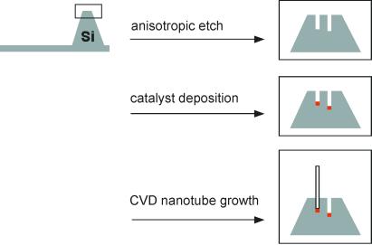
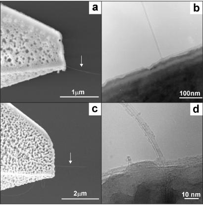
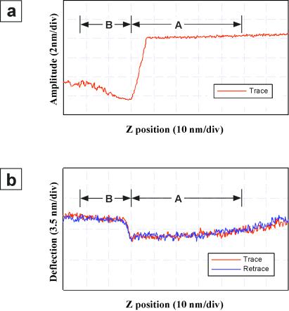
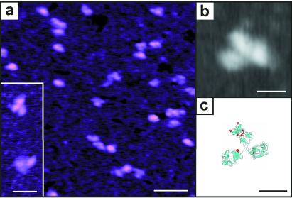
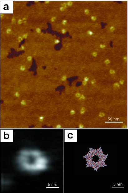
Carbon nanotubes are potentially ideal atomic force microscopy probes because they can have diameters as small as one nanometer, have robust mechanical properties, and can be specifically functionalized with chemical and biological probes at the tip ends. This communication describes methods for the direct growth of carbon nanotube tips by chemical vapor deposition (CVD) using ethylene and iron catalysts deposited on commercial silicon-cantilever-tip assemblies. Scanning electron microscopy and transmission electron microscopy measurements demonstrate that multiwalled nanotube and single-walled nanotube tips can be grown by predictable variations in the CVD growth conditions. Force-displacement measurements made on the tips show that they buckle elastically and have very small (</= 100 pN) nonspecific adhesion on mica surfaces in air. Analysis of images recorded on gold nanoparticle standards shows that these multi- and single-walled carbon nanotube tips have radii of curvature of 3-6 and 2-4 nm, respectively. Moreover, the nanotube tip radii determined from the nanoparticle images are consistent with those determined directly by transmission electron microscopy imaging of the nanotube ends. These molecular-scale CVD nanotube probes have been used to image isolated IgG and GroES proteins at high-resolution.
Figures
References
-
- Bustamante C, Rivetti C, Keller D J. Curr Opin Struct Biol. 1997;7:709–716. - PubMed
-
- Hansma H G, Kim K J, Laney D E, Garcia R A, Argaman M, Allen M J, Muller D S, Parsons S M. J Struct Biol. 1997;119:99–108. - PubMed
-
- Muller D J, Fotiadis D, Engel A. FEBS Lett. 1998;430:105–111. - PubMed
-
- Shao Z, Mou J, Czajkowsky J, Yang J, Yuan J. Adv Phys. 1996;45:1–86.
-
- Noy A, Vezenov D V, Lieber C M. Annu Rev Mater Sci. 1997;27:381–421.
MeSH terms
Substances
LinkOut - more resources
Full Text Sources
Other Literature Sources
