. 2000 May 1;149(3):635-46.
doi: 10.1083/jcb.149.3.635.

Isoforms of alpha-actinin from cardiac, smooth, and skeletal muscle form polar arrays of actin filaments

Affiliations

Isoforms of alpha-actinin from cardiac, smooth, and skeletal muscle form polar arrays of actin filaments

K A Taylor et al. J Cell Biol. .

Abstract

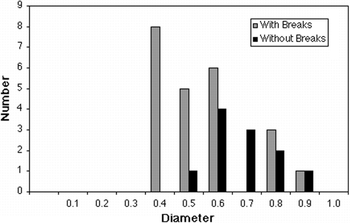
We have used a positively charged lipid monolayer to form two-dimensional bundles of F-actin cross-linked by alpha-actinin to investigate the relative orientation of the actin filaments within them. This method prevents growth of the bundles perpendicular to the monolayer plane, thereby facilitating interpretation of the electron micrographs. Using alpha-actinin isoforms isolated from the three types of vertebrate muscle, i.e., cardiac, skeletal, and smooth, we have observed almost exclusively cross-linking between polar arrays of filaments, i.e., actin filaments with their plus ends oriented in the same direction. One type of bundle can be classified as an Archimedian spiral consisting of a single actin filament that spirals inward as the filament grows and the bundle is formed. These spirals have a consistent hand and grow to a limiting internal diameter of 0.4-0.7 microm, where the filaments appear to break and spiral formation ceases. These results, using isoforms usually characterized as cross-linkers of bipolar actin filament bundles, suggest that alpha-actinin is capable of cross-linking actin filaments in any orientation. Formation of specifically bipolar or polar filament arrays cross-linked by alpha-actinin may require additional factors that either determine the filament orientation or restrict the cross-linking capabilities of alpha-actinin.


Figures

Figure 1
Figure 1
Arrays of actin filaments cross-linked with α-actinin from (a) skeletal muscle, (b) smooth muscle, (c) cardiac muscle, and (d) Dictyostelium discoidium, a nonmuscle isoform. In all three cases, the morphology of the bundles is similar, including the insertion of filaments into the bundle. Arrows denote filament insertions. Note that insertion does not disrupt the cross-linking after the filament spacing has adjusted to the optimal amount. There is also no alteration in the preferred attachment angle of the cross-linkers once the filament spacing has adjusted, suggesting that the filaments are incorporated in the same orientation as the previously cross-linked filaments. The bundles shown in b and c are portions of spirals.
Figure 2
Figure 2
Array of actin filaments cross-linked by rabbit erector spinae muscle α-actinin. Typically, one or two α-actinin cross-links form within each crossover period between adjacent filaments. Paired links can be either parallel to each other or differently angled to produce triangular struts between actin filaments. The unit cell has dimensions of a = 45.4 nm, b = 112.1 nm, γ = 120.4°, and contains only one actin filament. The interfilament spacing is 39.1 nm. (b) Computed diffraction pattern from the region outlined in a. Sampling on all layer lines indicates that the actin filaments in the array are oriented in the same direction. The helical structure of the actin filaments is 41 subunits in 19 turns of the 5.9-nm genetic helix. (c) Filtered image of the region outlined in a.
Figure 3
Figure 3
α-Actinin–F-actin spiral figures. (Upper panel) Spiral figure of one actin filament cross-linked with skeletal muscle α-actinin. The two segments of actin filament cross-linked by α-actinin are always oriented in the same direction; the resulting bundle is always polar. (Lower panel) Drawing indicating the path of the filaments and the position of the most clearly identified cross-links. When viewed in a direction from the solution phase onto the monolayer, the spirals coil in a left-handed (clockwise) sense, as the filament grows inward from the outside. The arrows indicate the start and end of the continuous filament run. After the long segment stops growing, at the center of the bundle, additional filaments grow for short periods and they too stop. The beginning and ending points of these filament fragments are indicated by arrowheads in the upper panel.
Figure 4
Figure 4
Histogram showing the range of internal diameters of actin spirals cross-linked by α-actinin. Many spirals are not perfectly circular. Some have oval or ellipsoidal shapes. In these cases, the width of the minor axis was taken to be the limiting diameter. In cases where the shape was more irregular, we attempted to draw a circle tangential to the actin filament at the point of the break.
Figure 5
Figure 5
(Upper panel) Electron micrograph of a spiral figure formed from G-actin polymerization alone. Arrows indicate the start and end of the continuous filament. (Lower panel) Drawing of the continuous filament. In the center, the short lengths of the filaments have condensed into a paracrystalline raft near the arrow.
Figure 6
Figure 6
Filament arrangements in bipolar 3-D bundles with random filament orientations. This particular bundle was adapted from Fig. 4 a of Francis and DeRosier 1990. There are 19 filaments in the bundle (9 in one orientation and 10 in the other). The actin filaments occur in random orientations with respect to + or − directions, with the added constraint that any triplet contains two filaments in one orientation and one in the other. Open and filled circles represent the two filament orientations. Bipolar cross-links (C-shaped) have been drawn so that they begin and end on one side of the center line adjoining the two filaments. A local twofold symmetry axis centered on the cross-link is possible for this positioning. Polar cross-links (sigmoid shape) cross the center line to bind the other side of the neighboring actin filament. In projection, a polar cross-link would appear to have twofold symmetry about an axis parallel to the filaments and through the cross-link. However, an actual twofold axis would require that the cross-link be perpendicular to the filament axis. (a–c) Crosslinking pattern between nearest neighbor filaments. (a) Polar nearest neighbor cross-links. (b) Bipolar nearest neighbor cross-links. (c) Complete pattern of 42 nearest neighbor cross-links, of which 12 are polar (28%) and 30 are bipolar (72%). Note that cross-links can be drawn without crossing each other. (d–f) The same bipolar actin bundle shown in a but with cross-links drawn to next nearest neighbor filaments. (d) Next nearest neighbor polar cross-linking pattern. (e) Next nearest neighbor bipolar cross-linking pattern. (f) Overall next nearest neighbor cross-linking pattern. In this case there are only 30 cross-links, 6 of which are bipolar (20%) and 24 of which are polar (80%), which is the opposite trend for nearest neighbor cross-linkers. Note also that in this arrangement, cross-links drawn in this planar view cross each other, unlike for the nearest neighbor cross-links. This does not necessarily mean that they interfere with each other, since the actual pattern has 3-D depth to it.
Figure 7
Figure 7
Diagram showing the relative positions of filaments and cross-links in 2-D bundles formed on a lipid surface. (a and b) Bipolar 2-D bundle in (a) longitudinal and (b) transverse view down the filament axis. Note that free cross-linkers must approach from the side opposite from the monolayer, which may make actin monomers appropriately oriented for cross-linking between alternate filament pairs relatively inaccessible. In the accessible orientation, the cross-link is distant from the lipid surface and probably cannot be stabilized by lipid binding. In the less accessible position close to the monolayer, the cross-linker can be stabilized by lipid binding. (c and d) Polar 2-D bundle in (c) longitudinal and (d) transverse view. Note that in this orientation, each filament pair has equal accessibility to cross-linker and that the cross-linker also is accessible over at least part of its surface to the lipid layer.

References

    1. Arai Y., Yasuda R., Akashi K., Harada Y., Miyata H., Kinosita K., Itoh H. Tying a molecular knot with optical tweezers. Nature. 1999;399:446–448. - PubMed
    1. Astier C., Labbé J.-P., Roustan C., Benyamin Y. Effects of different enzymic treatments on the release of titin fragments from rabbit skeletal myofibrils. Biochem. J. 1993;290:731–734. - PMC - PubMed
    1. Atsuta F., Sato K., Maruyama K., Shimada Y. Distribution of connectin (titin), nebulin and α-actinin at myotendinous junctions of chicken pectoralis musclesan immunofluorescence and immunoelectron microscopic study. J. Muscle Res. Cell Motil. 1993;14:511–517. - PubMed
    1. Blanchard A., Ohanian V., Critchley D. The structure and function of α-actinin. J. Muscle Res. Cell Motil. 1989;10:280–289. - PubMed
    1. Burn P., Rotman A., Meyer R.K., Burger M.M. Diacylglycerol in large α-actinin/actin complexes and the cytoskeleton of activated platelets. Nature. 1985;314:469–472. - PubMed

Publication types