. 2001 Jan 15;20(1-2):65-76.
doi: 10.1093/emboj/20.1.65.

Role of elementary Ca(2+) puffs in generating repetitive Ca(2+) oscillations

Affiliations

Role of elementary Ca(2+) puffs in generating repetitive Ca(2+) oscillations

J S Marchant et al. EMBO J. .

Abstract

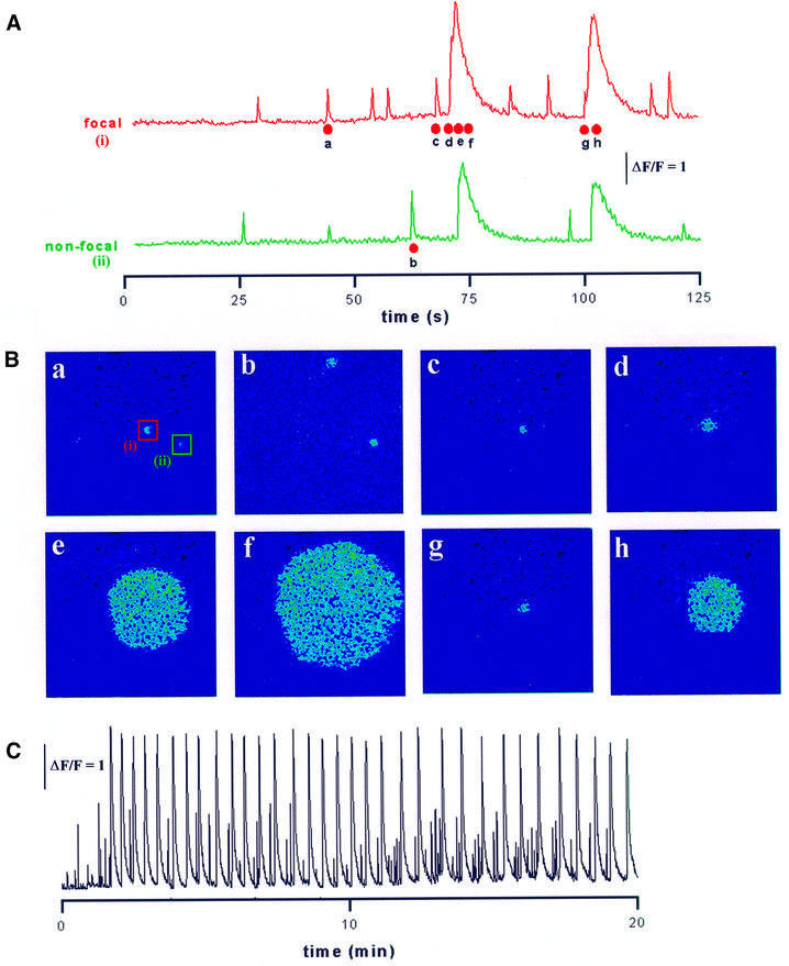
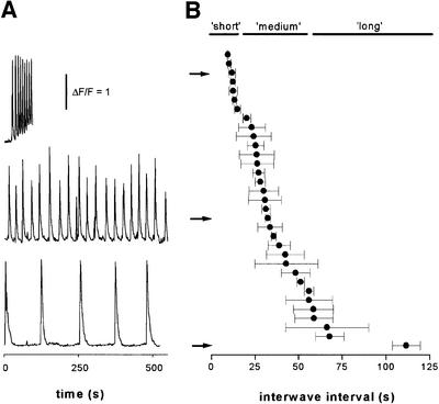
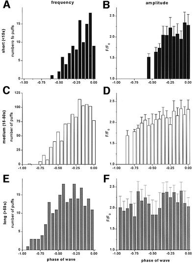
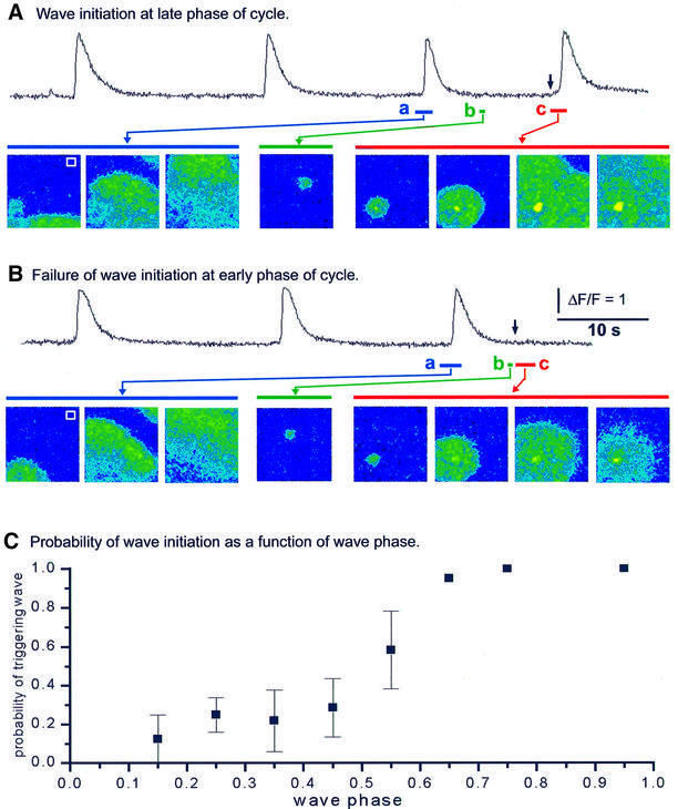
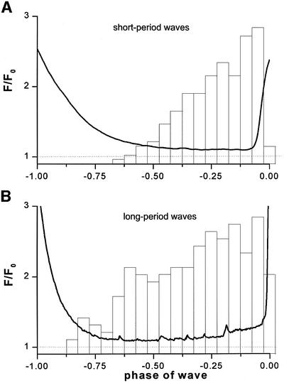
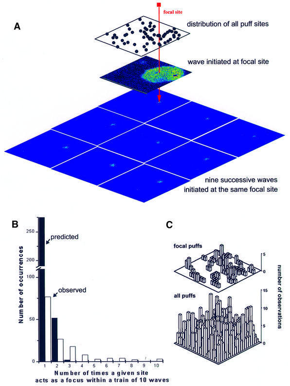
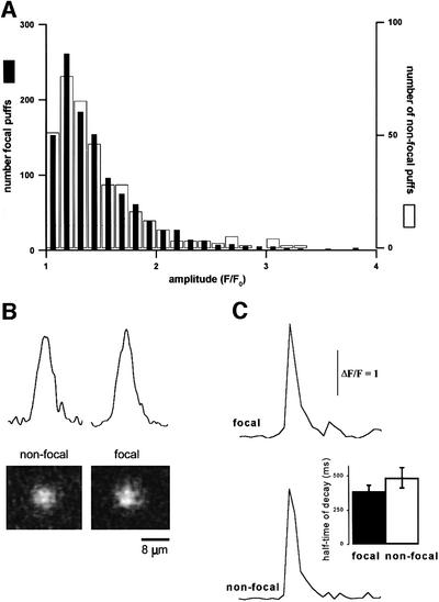
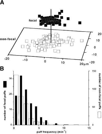
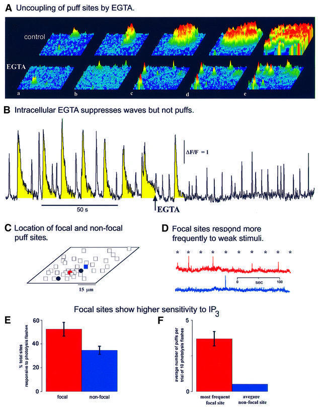
Inositol (1,4,5)-trisphosphate (IP(3)) liberates intracellular Ca(2+) both as localized 'puffs' and as repetitive waves that encode information in a frequency-dependent manner. Using video-rate confocal imaging, together with photorelease of IP(3) in Xenopus oocytes, we investigated the roles of puffs in determining the periodicity of global Ca(2+) waves. Wave frequency is not delimited solely by cyclical recovery of the cell's ability to support wave propagation, but further involves sensitization of Ca(2+)-induced Ca(2+) release by progressive increases in puff frequency and amplitude at numerous sites during the interwave period, and accumulation of pacemaker Ca(2+), allowing a puff at a 'focal' site to trigger a subsequent wave. These specific 'focal' sites, distinguished by their higher sensitivity to IP(3) and close apposition to neighboring puff sites, preferentially entrain both the temporal frequency and spatial directionality of Ca(2+) waves. Although summation of activity from many stochastic puff sites promotes the generation of regularly periodic global Ca(2+) signals, the properties of individual Ca(2+) puffs control the kinetics of Ca(2+) spiking and the (higher) frequency of subcellular spikes in their local microdomain.


Figures

None
Fig. 1. Induction of puffs and periodic Ca2+ waves by sustained photorelease of IP3. (A) Measurements of Ca2+-dependent fluorescence monitored from 8 × 8 µm regions centered on two puff sites (i and ii) within the imaging field. The UV photolysis light was turned on at the start of the record, and remained on thereafter. Photoreleased IP3 initially evoked asynchronous puffs at these sites (and at many other sites not shown), and a puff at site (i) triggered a Ca2+ wave that propagated throughout the imaging field. Puff activity ceased during the falling phase of the wave, but subsequently recovered until a second wave was again triggered by a puff at site (i). (B) Single image frames illustrating the spatial patterns of cytosolic Ca2+ observed at times corresponding to the points marked in (A). The sites from which the traces in (A) were obtained are marked on frame B (a). Panels depict Ca2+-dependent fluorescence on a pseudo-color scale, after subtraction of resting fluorescence before stimulation. (C) Fluorescence trace from site (i) shown on a slower time scale illustrating periodic Ca2+ waves during sustained photolysis for 20 min.
None
Fig. 2. Increasing photorelease of IP3 evokes waves with progressively shorter periods. (A) Fluorescence traces (monitored from 8 × 8 µm boxes) from three different oocytes, exposed to UV light of constant intensity throughout each record. Repetitive waves with a mean period of ∼10 s were evoked in the top record by relatively strong UV illumination, whereas the middle and lower traces show waves with periods of ∼30 and ∼110 s in response to progressively weaker stimuli. (B) The plot shows mean interwave intervals from 33 trials like those in (A), illustrating the range of periods explored. Error bars indicate 1 SD of the period derived from all successive waves during each trial. Arrows indicate data points corresponding to the traces in (A), and the bars show the arbitrary grouping of the data set into ‘short’-, ‘medium’- and ‘long’-period records.
None
Fig. 3. Measurements of puff frequency and amplitude plotted as a function of phase of the wave cycle. Data are derived from the data set of Figure 2B, and were analyzed separately after grouping together records displaying waves with short (<15 s), medium (15–50 s) and long (>50 s) periods. (A, C and E) Histograms show the relative numbers of puffs observed throughout the entire imaging field (expressed as a percentage of the maximum) at different phases of the wave cycle. A phase of ‘0’ corresponds to the peak of one wave, and a phase of ‘–1’ to the peak of the preceding wave. (B, D and F) Corresponding histograms showing the distributions of peak fluorescence amplitudes (F/F0) of these puffs.
None
Fig. 4. The cytoplasm recovers the ability to propagate Ca2+ waves early during the wave cycle. (A and B) Experimental protocol using a laser ‘zap’ technique to probe the excitability of the cell. Repetitive Ca2+ waves were induced by injection of I(2,4,5)P3. After recording three spontaneous waves, a laser pulse was delivered at various times so as to evoke a localized Ca2+ elevation near the bottom left corner of the imaging field. The traces in each section show fluorescence monitored near the top right corner of the field (white boxes), and the sequences of images show selected frames captured when indicated by the bars under the traces. Images illustrate (a) the propagation of periodic Ca2+ waves, (b) spontaneous Ca2+ puffs and (c) responses to a laser zap delivered when marked by the arrows above the traces. In (A), the laser zap was delivered relatively late during the wave cycle, and the local exogenous Ca2+ elevation triggered a Ca2+ wave that propagated throughout the imaging frame. In (B), the laser zap was delivered at an early phase during the wave cycle and failed to trigger a Ca2+ wave. (C) The plot shows the probability of triggering of Ca2+ waves by laser zaps delivered at varying phases throughout the wave cycle. Data were obtained from experiments like those in (A) and (B), from measurements during 57 trials (five oocytes) with wave periods of 15–30 s.
None
Fig. 5. The basal Ca2+ level around focal sites increases slowly before each wave during long-period spiking, but not during short-period spiking. (A) The solid trace shows the basal Ca2+ fluorescence signal in the vicinity of focal puff sites as a function of wave phase for short-period (<15 s) waves. This is an average from 32 sites, obtained by measuring the mean fluorescence ratio within 8 × 8 µm regions centered on focal puff sites. A ratio of F/F0 = 1 (dashed line) corresponds to the resting Ca2+ level before photorelease of IP3. The superimposed histogram shows, for comparison, the corresponding increase in puff frequency, replotted from Figure 3A and aligned to the time of wave initiation. (B) Similar data obtained during long-period (>50 s) waves.
None
Fig. 6. Waves are triggered preferentially at specific, focal puff sites. (A) Images illustrating the initiation of nine successive Ca2+ waves (period ∼50 s) at a single, focal puff site. The upper panel shows the distribution of all 58 puff sites observed throughout the imaging field during a 35 min record. The middle panel shows a circular wave that originated at the focal site marked in red. The lower mosaic of nine panels shows images captured at the beginning of nine successive waves, that all originated at the same site. (B) Experimental (open bars) and predicted (solid bars) distributions of occurrences where n (1, 2, 3, etc.) waves out of a train of 10 arose at a given site. Experimental data were obtained from 33 records, measuring the first 10 waves in each train (i.e. 330 waves in total). The mean number of puff sites within the imaging field was 40 (1288 sites in 33 records). The predicted distribution was obtained assuming 40 puff sites per field, which all had an equal probability of wave initiation. To simulate this situation, we generated 33 sequences of 10 random integer numbers within the range 1–40, and counted the numbers of occurrences where a given integer (corresponding to a particular site puff site) arose n times within each set of 10. (C) Focal and non-focal puffs sites are located randomly throughout the imaging field. Plots show distributions of focal (top) and non-focal (bottom) puff sites within a 65 × 65 µm imaging plane, scored by position within a grid of individual ∼10 µm2 regions. Measurements were made in 33 oocytes, from records such as those shown in (A).
None
Fig. 7. Puffs at focal sites display similar amplitudes and kinetics to those at non-focal sites. (A) Histograms show distributions of peak puff amplitudes at focal (filled bars) and non-focal (open bars) sites. Measurements were made as peak fluorescence ratio (F/F0) measured within an 8 × 8 µm box centered at puff sites. Data (1100 focal events, 350 non-focal events; 33 oocytes) were obtained during repetitive waves with periods of 10–110 s. Puffs that directly triggered waves were excluded. Representative non-focal sites were selected using a random number generator. (B) The spatial spread of puffs is similar at focal and non-focal sites. Images show averaged puffs at focal (n = 14) and non-focal (n = 18) sites, formed by capturing individual frames at the time of maximal puff amplitude averaging after spatially aligning their centers. Traces show corresponding fluorescence profiles measured along a line (3 pixel width) passing diametrically through the centers of the averaged events. (C) Puffs at focal and non-focal sites show similar decay times. Traces show kinetics of fluorescence signals measured from 8 × 8 pixel boxes centered on focal and non-focal puff sites. Records are averages of 14 focal and 18 non-focal events. The histogram plots the mean half-time for decay of fluorescence at focal (n = 14) and non-focal sites (n = 18).
None
Fig. 8. Focal sites are located closer to neighboring sites than are non-focal sites, and exhibit a higher frequency of puffs. (A) The scatter plot shows the locations of the nearest neighboring puff site with respect to selected focal sites (filled squares, n = 141) and randomly selected non-focal sites (open squares, n = 168). The plot was generated by aligning each selected site (focal or non-focal) at the center of the field (vertical line) and then mapping the position of the nearest neighboring puff site. (B) Distribution of puff frequencies at focal (filled bars; left axis) and non-focal (open bars; right axis) puff sites. Data were obtained from 33 records (five frogs).
None
Fig. 9. Focal wave initiation sites display an intrinsically higher sensitivity to IP3. (A) Image sequences illustrating the functional uncoupling of puff sites following intracellular loading of the slow Ca2+ buffer EGTA. Each image sequence (a–e) was captured at intervals of 100 ms, and illustrates the patterns of Ca2+ liberation evoked in an oocyte by a photolysis flash of fixed intensity before (top) and after (bottom) loading EGTA to a final intracellular concentration of ∼300 µM. The flash evoked a propagating Ca2+ wave in control conditions, but gave only discrete puffs after loading EGTA. Records were obtained from a 65 µm2 region of the animal hemisphere, in response to photolysis flashes delivered just before the image sequences. (B) Abolition of Ca2+ waves by EGTA. Fluorescence signals were measured from an 8 µm2 region centered on a puff site in response to sustained photorelease of IP3 throughout the entire record. Repetitive Ca2+ waves (highlighted in yellow) and puffs were evoked in control conditions. The waves were abolished rapidly following injection of EGTA (arrowed), but puffs continued with little change in amplitude or frequency. (C) Schematic diagram, illustrating the protocol for measuring the relative sensitivities of puff sites. The locations of focal (filled circles) and non-focal puff sites (open squares) within the 65 µm2 imaging plane were mapped during sustained photorelease of IP3 as in (B). EGTA was then injected, and responses were monitored from the same puff sites in response to weak photolysis flashes. (D) The traces show puffs evoked at representative focal and non-focal sites (marked in C by the red circle and blue square, respectively), in response to a train of 10 photolysis flashes delivered at 30 s intervals as marked by the asterisks. (E) Percentages of focal sites (red) and non-focal sites (blue) that gave one or more puffs during a train of 10 photolysis flashes. (F) Average numbers of puffs evoked per 10 flashes at frequent focal puff sites (red) and representative non-focal sites (blue).

References

    1. Berridge M.J. (1997a) The AM and FM of calcium signalling. Nature, 386, 759–760. - PubMed
    1. Berridge M.J. (1997b) Elementary and global aspects of calcium signalling. J. Physiol., 499, 291–306. - PMC - PubMed
    1. Berridge M.J. and Dupont,G. (1994) Spatial and temporal signalling by calcium. Curr. Opin. Cell Biol., 6, 267–274. - PubMed
    1. Bezprozvanny I., Watras,J. and Ehrlich,B.E. (1991) Bell-shaped calcium-response curves for Ins(1,4,5)P3- and calcium-gated channels from endoplasmic reticulum of cerebellum. Nature, 351, 751–754. - PubMed
    1. Bootman M.D., Niggli,E., Berridge,M.J. and Lipp,P. (1997a) Imaging the hierarchical Ca2+ signalling system in HeLa cells. J. Physiol., 499, 307–314. - PMC - PubMed

Publication types