. 2001 Aug 1;20(15):4107-21.
doi: 10.1093/emboj/20.15.4107.

Propagation of the apoptotic signal by mitochondrial waves

Affiliations

Propagation of the apoptotic signal by mitochondrial waves

P Pacher et al. EMBO J. .

Abstract

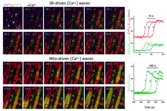
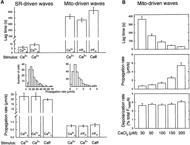
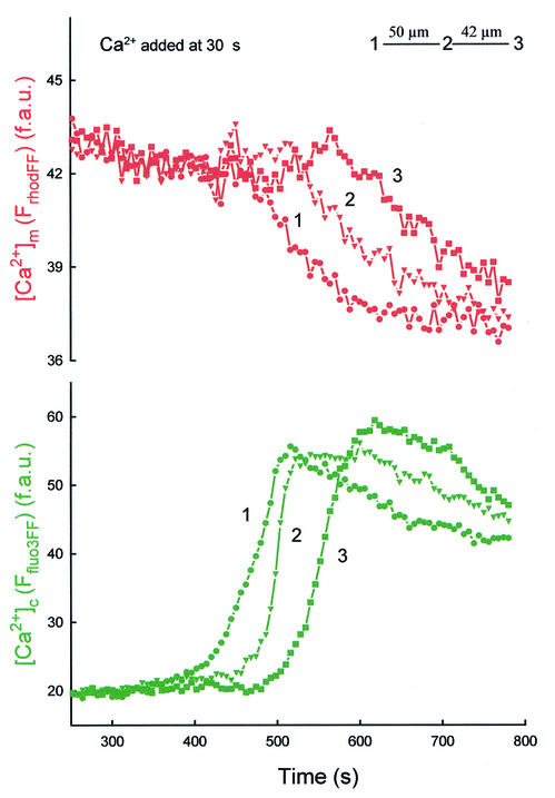
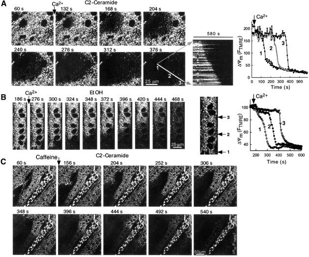
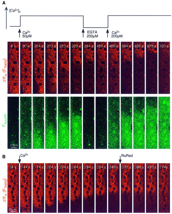
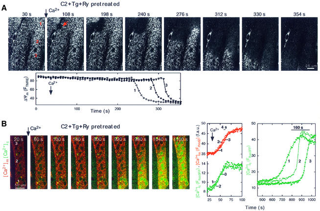
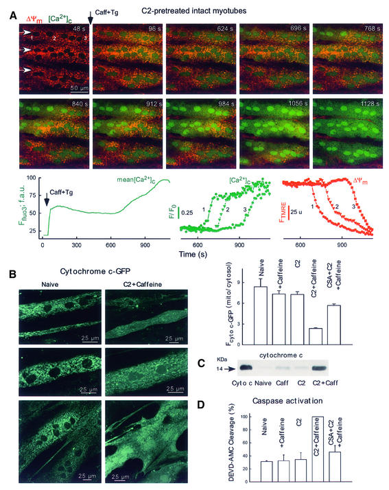
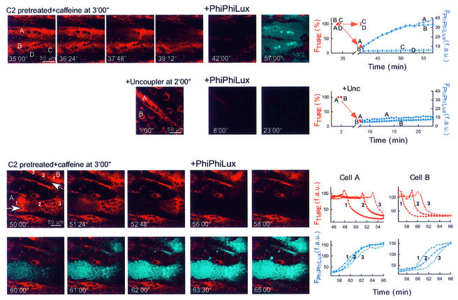
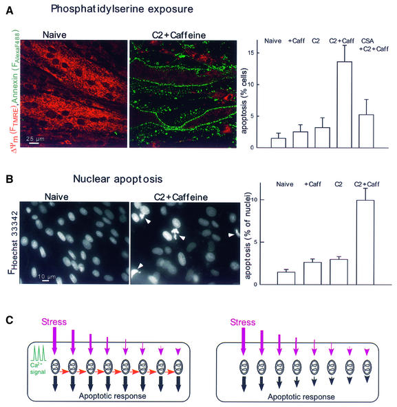
Generation of mitochondrial signals is believed to be important in the commitment to apoptosis, but the mechanisms coordinating the output of individual mitochondria remain elusive. We show that in cardiac myotubes exposed to apoptotic agents, Ca2+ spikes initiate depolarization of mitochondria in discrete subcellular regions, and these mitochondria initiate slow waves of depolarization and Ca2+ release propagating through the cell. Traveling mitochondrial waves are prevented by Bcl-x(L), involve permeability transition pore (PTP) opening, and yield cytochrome c release, caspase activation and nuclear apoptosis. Mitochondrial Ca2+ uptake is critical for wave propagation, and mitochondria at the origin of waves take up Ca2+ particularly effectively, providing a mechanism that may underlie selection of the initiation sites. Thus, apoptotic agents transform the mitochondria into an excitable state by sensitizing PTP to Ca2+. Expansion of the local excitation by mitochondrial waves propagating through the whole cell can be especially important in activation of the apoptotic machinery in large cells.


Figures

None
Fig. 1. SR- and mitochondria-driven [Ca2+] waves in C2-pretreated permeabilized cardiac myotubes. Simultaneous confocal imaging of [Ca2+]c and [Ca2+]m using fluo3FF added to the incubation medium and compartmentalized rhod2. The upper two rows of Ffluo3FF and Frhod2 images (presented as green–red overlays) show that Ca2+-induced (30 μM CaCl2) Ca2+ release from SR resulted in a [Ca2+]c wave that was associated with a [Ca2+]m wave. The upper graph shows corresponding traces of [Ca2+]m and [Ca2+]c calculated for three subregions of the cell (marked by numbers, ∼30 pixels each) chosen to be in line with the apparent direction of wave propagation. As shown in the lower two rows of images, the first [Ca2+]c wave was followed by a second [Ca2+]c wave. Although both [Ca2+]c waves originated from the same region and exhibited the same propagation pattern, the second wave was ∼10 times slower and appeared as a substantially larger [Ca2+]c increase. The lower graph shows the time course of the mitochondria-driven [Ca2+]c wave at the subregions shown in the upper panel. Note the different time scales used for presentation of the first and second waves.
None
Fig. 2. Kinetic properties of waves originated from SR and mitochondria. (A) Comparison of the lag time and propagation rate of waves driven by SR and mitochondria in C2-pretreated permeabilized myotubes. [Ca2+] and ΔΨm waves were triggered by addition of a Ca2+ pulse (30 µM CaCl2) or caffeine (10 mM) and were monitored as described in Figures 1, 4 and 5 (n = 23–162 for each condition). (B) Effect of [Ca2+]c on lag time, propagation rate of ΔΨm waves and rate of depolarization (n = 40–57). Depolarization rates were normalized to the total ΔFTMRE.
None
Fig. 3. Decrease in [Ca2+]m during mitochondria-driven [Ca2+]c waves. Measurement of [Ca2+]m was carried out using a low affinity Ca2+ tracer, rhod2FF, simultaneously with measurement of [Ca2+]c using fluo3FF. [Ca2+]c waves were evoked as described in Figure 1. The graph shows traces of [Ca2+]m and [Ca2+]c calculated for three subregions of the cell chosen to be in line with the apparent direction of wave propagation.
None
Fig. 4. Waves of Ca2+ signal-induced mitochondrial depolarization in permeabilized myotubes exposed to C2 or EtOH. Confocal image time series of TMRE fluorescence show the spatial pattern of depolarization evoked by Ca2+ (A and B; two pulses of 50 µM CaCl2 each) and 10 mM caffeine + 10 µM CaCl2 (C) in permeabilized H9c2 myotubes exposed to C2 (A and C; 40 µM for 5 min) or EtOH (B; 35 mM for 48 h). Although caffeine by itself elicited mitochondrial depolarization in C2-pretreated cells (see Results), in the experiments shown in the figures caffeine was added together with 10 µM CaCl2 to optimize Ca2+ loading of the intracellular stores. Graphs show time courses of TMRE fluorescence for regions selected along the path of wave propagation (marked with numbers).
None
Fig. 5. Mitochondrial depolarization and Ca2+ release waves depend on cytosolic [Ca2+] rise and mitochondrial Ca2+ uptake. (A) Simultaneous confocal imaging of [Ca2+]c and ΔΨm carried out in permeabilized H9c2 myotubes. The fluorescence intensities of TMRE and fluo3FF reflecting ΔΨm and [Ca2+]c are depicted on linear red and green scales, respectively. Importantly, the fluo3FF confocal images reflect [Ca2+]c changes in the selected focus plane. Therefore, rapid Ca2+ mobilization from intracellular stores is associated with fluo3FF responses even if a global [Ca2+]c rise does not occur. The plot above the confocal image time series shows the time course profile of global [Ca2+] changes in the cytosolic buffer. Waves were elicited in C2-treated permeabilized cells by addition of 50 µM CaCl2 and subsequently stopped by addition of a Ca2+ chelator (200 µM EGTA). When global [Ca2+]c was increased again, propagation of the waves continued the original spatial pattern. Changes in pH in the incubation medium associated with addition of EGTA and Ca2+ were <0.1 units. (B) Inhibition of the Ca2+-induced depolarization wave by RuRed (2 µM) in a C2-pretreated permeabilized myotube. Confocal image time series displays TMRE fluorescence on a linear red scale. As this experiment was carried out using cells pretreated with Tg (2 µM) and Ry (200 µM), inhibition of RyR by RuRed did not account for the effect of RuRed on wave propagation.
None
Fig. 6. Mitochondria-driven waves in cells with inhibited SR Ca2+ transport. (A) Confocal image time series showing a propagating depolarization wave evoked by addition of Ca2+ (50 µM CaCl2) in a permeabilized H9c2 cell pretreated with Tg (2 µM) + Ry (200 µM) + C2 (40 µM). The fluorescence intensity of TMRE reflecting ΔΨm is shown using grayscale. Time courses of the FTMRE changes are shown at three intracellular regions selected along the path of wave propagation. (B) Image time series showing a mitochondria-driven [Ca2+]c wave in a permeabilized myotube pretreated with Tg + Ry + C2. Simultaneous confocal imaging of [Ca2+]c (green) and [Ca2+]m (red) was carried out using fluo3FF and compart mentalized rhod2 as described in Figure 5. In contrast to the results shown in Figure 1, addition of Ca2+ did not evoke SR-driven waves (images: 60, 100, 140 s and graphs). However, after >10 min lag time, a slowly propagating large amplitude [Ca2+]c wave appeared, similarly to the mitochondrial wave shown in Figure 5. The right graph shows time courses (green) calculated for the marked subcellular regions.
None
Fig. 7. Mitochondria-driven waves, cyto c release and caspase activation in intact myotubes. (A) Simultaneous confocal imaging of [Ca2+]c and ΔΨm carried out in intact H9c2 myotubes. Fluorescence intensities of TMRE and fluo3 reflecting ΔΨm and [Ca2+]c are depicted on linear red and green scales, respectively. Waves were elicited in C2-pretreated cells (40 µM for 5 h) by addition of caffeine (15 mM) and Tg (2 µM). Arrows in the top left panel show the direction of wave propagation. The graphs show the mean time course profile of [Ca2+]c for the total area of the upper myotube (left) and time courses of [Ca2+]c (middle) and ΔΨm (right) at three intracellular regions selected along the path of wave propagation (50 pixels each, marked with numbers). (B) Cyto c–GFP distribution in intact myotubes. For the experiments shown in (B–D), the adherent myotubes were pre-incubated with C2 (40 µM) or C2 + CSA (1 µM) or solvent for 2 h and, subsequently, 15 mM caffeine or solvent was also added for 4 h. The stimulation protocol is described in detail in Materials and methods. As a quantitative measure of cyto c–GFP release, the mean Fcyto c–GFP was calculated over the mitochondria and over the nucleus (used to assess cytosolic cyto c–GFP) for each cell and the ratios are plotted in the graph (61–191 myotubes). (C) Immunoblots showing cyto c in cytosol samples generated from intact adherent myotubes treated as described in (B). Cyto c, 14 ng cyto c. (D) Caspase activity in cytosol samples generated from intact adherent myotubes (n = 3).
None
Fig. 8. Mitochondria-driven waves of caspase activation in intact myotubes. Simultaneous imaging of ΔΨm and fluorescent caspase cleavage products in single intact adherent myotubes treated as described in Figure 7A. After the Ca2+ signal-induced depolarization wave or the uncoupler (FCCP 5 µM + oligomycin 10 µg/ml)-induced depolarization was completed, the buffer was replaced with RPMI containing 5 (upper and middle) or 10 µM (lower) cell-permeable fluorogenic caspase substrate (+ PhiPhiLux). Overlaid images of FTMRE (red) and FPhiPhiLux (blue) are shown.
None
Fig. 9. Ca2+ signal-induced apoptosis in C2-pretreated myotubes. (A) PS exposure visualized using annexin–Alexa Fluor 488 staining of intact myotubes treated as described in (B) (mean ± SE of values from 1776–2135 myotubes). Note that ΔΨm was measured simultaneously by annexin staining using TMRE. In myotubes with annexin–Alexa Fluor 488 staining, FTMRE was very low, suggesting large mitochondrial depolarization. (B) Nuclear apoptosis detected by staining with Hoechst 33342/propidium iodide (5670–9014 nuclei). Propidium iodide was excluded from >99% of naive, C2-treated and caffeine-stimulated cells and >98% of the C2 + caffeine treated myotubes, suggesting the absence of late apoptotic or necrotic cells. (C) Scheme showing how the apoptotic machinery can be controlled by local communication between mitochondria. The predicted responses to a non-uniform stress are shown for mitochondria acting in a coupled manner (left side) or mitochondria activated independently by the apoptotic stress (right side). In both cases, the subsets of mitochondria exposed to vigorous stress respond by rapid and maximal release of apoptotic factors. If these mitochondria also release factors that promote the apoptotic response of neighboring mitochondria (red arrows), apoptotic waves propagate through the cells and the entire mitochondrial population participates in the apoptotic response in a coordinated manner (left panel). By contrast, if there is no lateral signaling between mitochondria, the subsets of mitochondria that experienced less stress give less or slower apoptotic response (right panel).

References

    1. Alnemri E.S. (1999) Hidden powers of the mitochondria. Nature Cell Biol., 1, 40–42. - PubMed
    1. Bernardi P., Scorrano,L., Colonna,R., Petronilli,V. and Di Lisa,F. (1999) Mitochondria and cell death. Mechanistic aspects and methodological issues. Eur. J. Biochem., 264, 687–701. - PubMed
    1. Berridge M.J. (1997) The AM and FM of calcium signalling. Nature, 386, 759–760. - PubMed
    1. Berridge M.J., Bootman M.D. and Lipp,P. (1998) Calcium—a life and death signal. Nature, 395, 645–648. - PubMed
    1. Bers D.M. (1991) Excitation–Contraction Coupling and Cardiac Contractile Force. Kluwer Academic, Dordrecht, The Netherlands, pp. 1–258.

Publication types