. 2001 Sep 25;98(20):11301-5.
doi: 10.1073/pnas.191361398.

Digital in-line holography for biological applications

Affiliations

Digital in-line holography for biological applications

W Xu et al. Proc Natl Acad Sci U S A. .

Abstract

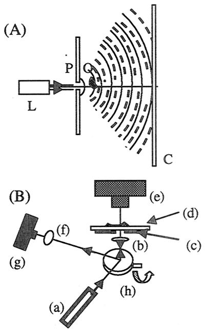
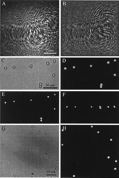
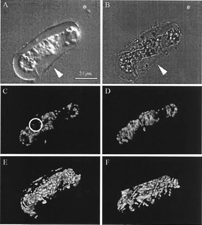
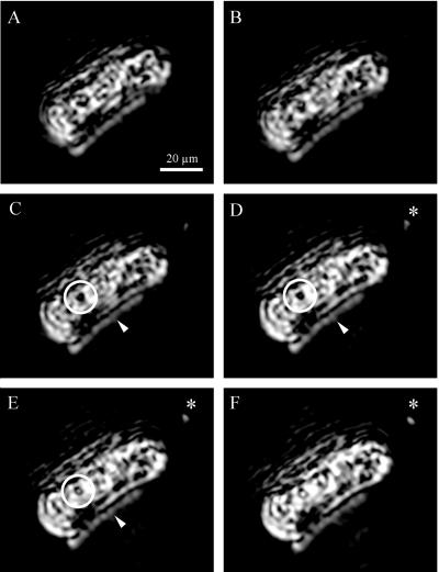
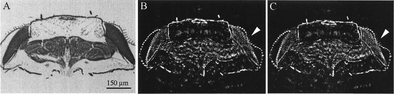
Digital in-line holography with numerical reconstruction has been developed into a new tool, specifically for biological applications, that routinely achieves both lateral and depth resolution, at least at the micron level, in three-dimensional imaging. The experimental and numerical procedures have been incorporated into a program package with a very fast reconstruction algorithm that is now capable of real-time reconstruction. This capability is demonstrated for diverse objects, such as suspension of microspheres and biological samples (diatom, the head of Drosophila melanogaster), and the advantages are discussed by comparing holographic reconstructions with images taken by using conventional compound light microscopy.


Figures

Figure 1
Figure 1
(A) Basic arrangement for in-line holography. A laser (L) illuminates a pinhole (P), which acts as a point source. Spherical waves from the pinhole illuminate the object (O), and the interference at the screen (C) of the scattered waves (– – –) with the reference wave (—) constitutes the hologram. (B) Schematic of the experimental arrangement used to record an optical image and a hologram of the same object. Eyepiece (f), camera (g), mirror (h), and objective lens (b) are part of an inverted microscope. To record the hologram, light from a laser (a) is reflected off the mirror and focused by the objective lens onto the pinhole (c). The light exiting the pinhole is passed through the object and glass substrate (d) and forms a hologram on the CCD chip (e). To record a conventional optical image of the object, the mirror is turned to allow white light from a lamp (not shown) that illuminates the object to reach a second CCD chip attached to the eyepiece.
Figure 2
Figure 2
Polymer microspheres (5.13 μm) mounted in gelatin. (A) Hologram (1,024 × 1,024 pixels); (B) contrast hologram; (C) bright-field compound microscope image (Zeiss, ×25/0.80 Plan Neofluar objective); (D) holographic 2-D reconstruction in a plane corresponding to C; (E and F) 3-D reconstruction from 15 2-D holographic reconstructions (of which D is number 8), by using a software package (amira) (E), viewed along the optical axis and (F) viewed from below at 90° to the optical axis. Pinhole–object distance, 1.5 mm; pinhole–CCD chip distance, 4.8 cm; green laser (A = 532 nm), 2-μm pinhole. (G and H) Polymer microspheres (1.09 μm) mounted in gelatin. (G) Bright-field compound microscope image (Zeiss, ×40/0.75 Plan Neofluar objective); (H) 2-D holographic reconstruction. Distance of object from pinhole, 0.875 mm; pinhole–CCD chip distance, 3.0 cm; blue laser (λ = 473 nm); 2-μm pinhole.
Figure 3
Figure 3
Single cell of D. brightwellii. (A) Differential interference microscopy obtained with Zeiss Plan Neofluar ×40/0.75 objective and (B) a bright-field image obtained in the transmission mode of a confocal microscope with ×40/1.30 oil immersion objective. Note resolution of the outer siliceous frustule (arrowhead) but poor contrast and depth resolution of cell contents in these two images. As a fortuitous marker, a single unidentified bacterium (asterisk) in A and B is attached to the frustule spine (B). (C and D) 3-D image stack of signal from specimen autofluorescence obtained by LSCM and reconstructed from 23 slices at 1-μm intervals, by using the same specimen and objective as B. Note contrast resolution of cell contents and absence of fluorescence in region enclosed by circle. (C) Viewed from same direction as in A and B; (D) reconstruction rotated 90° about the cell's long axis from the view in C. (E and F) 3-D reconstruction of the corresponding DIH image stack. (E) Same view as C, along the optical axis. (F) Rotated view, perpendicular to C, as in D.
Figure 4
Figure 4
Series of DIH sections at 0.46-μm intervals (sections 18–23 of the 49, from which the 3-D reconstructions in Fig. 3 E and F were obtained). Note the outline of the frustule (arrowhead in CE), identified by the size position and linear contours of such outlines, and by the similarity between the reconstructed form of the outlines in 3-D and the outline of the frustule in Fig. 3 A and B. Note also the cavity (circled), a likely vacuole, obscured by the outer portions of the cell in the reconstructed image (Fig. 3 E and F). The size of the bacterium (asterisk, DF) indicates the resolution attained (see Fig. 3 A and B). Blue laser, 2-μm pinhole; pinhole-object distance, 1.395 mm; pinhole–CCD chip distance, 3.0 cm.
Figure 5
Figure 5
Paraffin wax section, 10 μm thick, of the head of D. melanogaster, stained by the Bodian method. (A) Bright-field image obtained with conventional compound light microscope (Zeiss Axiophot; objective: ×10/0.3 Plan Neofluar). (B and C) Two DIH images of the same section as in A, by using the same objective, separated by a depth of 6.8 μm. This distance is sufficient to image different bristles over the compound eye, clearer in C (arrowhead) than in B. The head cuticle (arrowhead, B) has high image contrast, but at the contrast level required for DIH, some background material is visible surrounding the specimen. Blue laser; 2-μm pinhole; pinhole–object distance, 6.3 mm; pinhole–CCD chip distance, 6.9 cm.

References

    1. Gabor D. Nature (London) 1948;161:777–778. - PubMed
    1. Leith E N, Upatnieks J. J Opt Soc Am. 1962;52:1123–1130.
    1. Leith E N, Upatnieks J. J Opt Soc Am. 1963;53:1377.
    1. Leith E N, Upatnieks J. J Opt Soc Am. 1964;54:1295–1301.
    1. Kreis T. Holographic Interferometry. Berlin: Akademie; 1996.

Publication types

LinkOut - more resources