. 2001 Nov;75(22):10815-28.
doi: 10.1128/JVI.75.22.10815-10828.2001.

C terminus of infectious bursal disease virus major capsid protein VP2 is involved in definition of the T number for capsid assembly

Affiliations

C terminus of infectious bursal disease virus major capsid protein VP2 is involved in definition of the T number for capsid assembly

J R Castón et al. J Virol. 2001 Nov.

Abstract

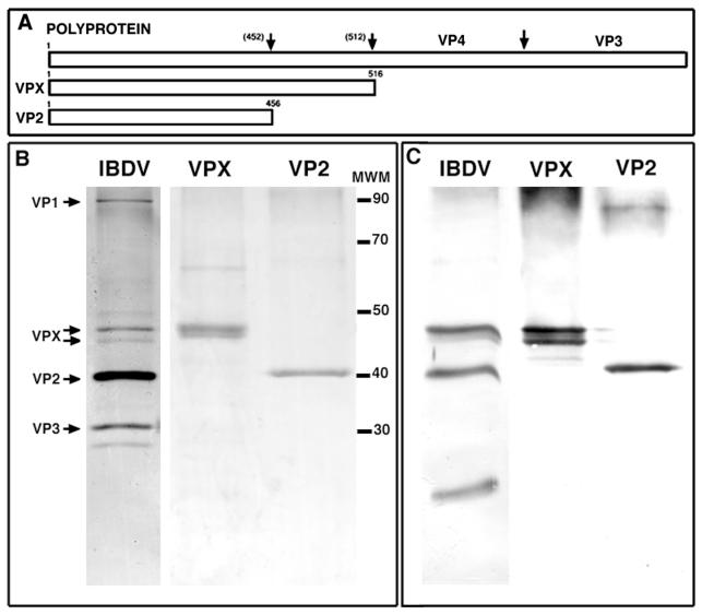
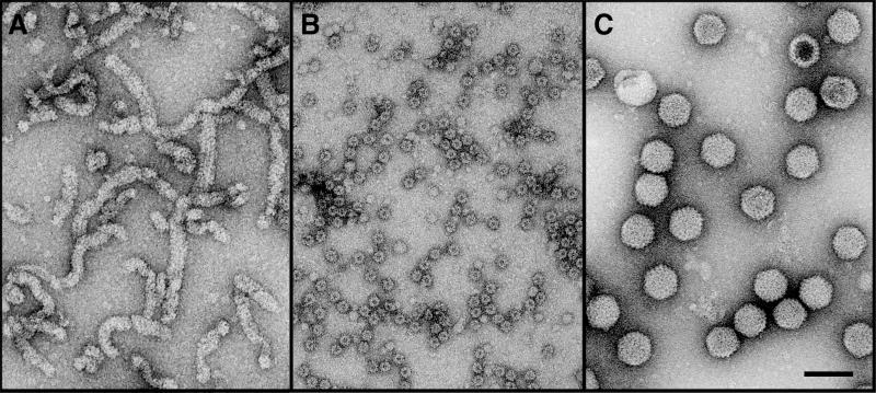
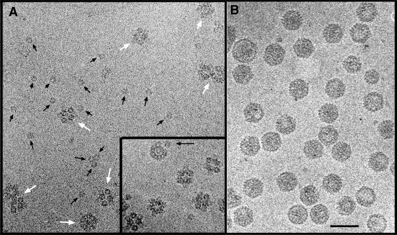
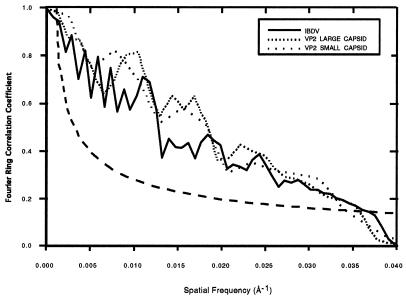
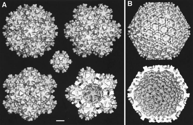
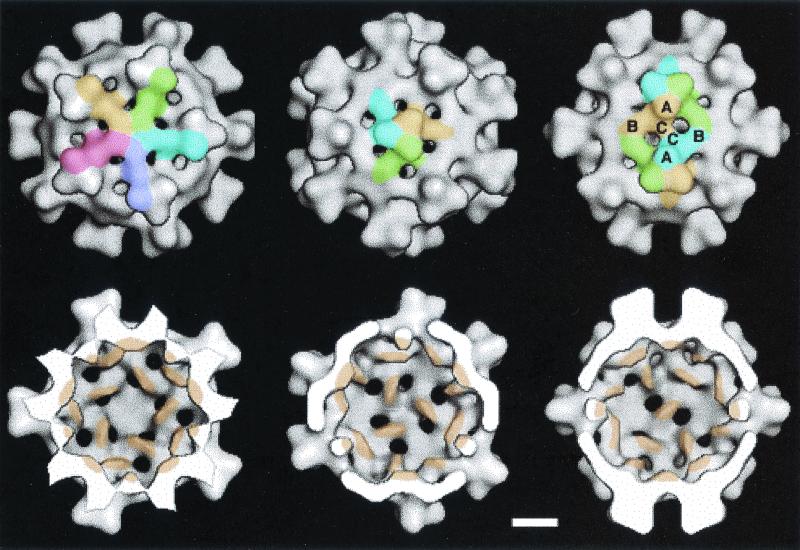
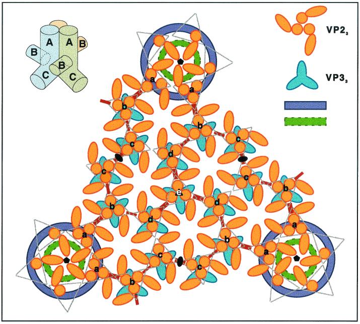
Infectious bursal disease virus (IBDV), a member of the Birnaviridae family, is a double-stranded RNA virus. The IBDV capsid is formed by two major structural proteins, VP2 and VP3, which assemble to form a T=13 markedly nonspherical capsid. During viral infection, VP2 is initially synthesized as a precursor, called VPX, whose C end is proteolytically processed to the mature form during capsid assembly. We have computed three-dimensional maps of IBDV capsid and virus-like particles built up by VP2 alone by using electron cryomicroscopy and image-processing techniques. The IBDV single-shelled capsid is characterized by the presence of 260 protruding trimers on the outer surface. Five classes of trimers can be distinguished according to their different local environments. When VP2 is expressed alone in insect cells, dodecahedral particles form spontaneously; these may be assembled into larger, fragile icosahedral capsids built up by 12 dodecahedral capsids. Each dodecahedral capsid is an empty T=1 shell composed of 20 trimeric clusters of VP2. Structural comparison between IBDV capsids and capsids consisting of VP2 alone allowed the determination of the major capsid protein locations and the interactions between them. Whereas VP2 forms the outer protruding trimers, VP3 is found as trimers on the inner surface and may be responsible for stabilizing functions. Since elimination of the C-terminal region of VPX is correlated with the assembly of T=1 capsids, this domain might be involved (either alone or in cooperation with VP3) in the induction of different conformations of VP2 during capsid morphogenesis.


Figures

FIG. 1
FIG. 1
Expression of VPX and VP2. (A) IBDV polyprotein structure, NH2-VPX-VP4-VP3-COOH. The recently suggested VPX–VP4 cleavage site at Ala512–Ala513 is indicated (46, 73). The cleavage site for conversion of VPX to the mature form of VP2 is around residues 450 to 456, but it is unknown. The VPX and VP2 forms used in this work are diagrammed below the polyprotein structure. (B) Expression of VPX and VP2 by AcVPX.IBDV and AcVP2.IBDV, respectively. Purified VPX and VP2 fractions (see Materials and Methods) were subjected to SDS-PAGE (11% polyacrylamide) and detected by Coomassie blue staining. Purified IBDV particles were subjected to the same treatment with silver staining. Bands corresponding to the VP1, VPX, VP2, and VP3 proteins are indicated. Molecular weight markers (MWM), in thousands, are given on the right.(C) Detection of VPX, VP2, and IBDV virions by Western blotting with polyclonal rabbit anti-VPX serum.
FIG. 2
FIG. 2
Electron microscopy of VPX and VP2 assemblies, compared with IBDV virions. (A) VPX twisted tubular structures; (B) VP2 doughnut-like structures; (C) purified IBDV virions. Bar, 100 nm.
FIG. 3
FIG. 3
Cryoelectron microscopy of VP2 assemblies, compared with IBDV virions. (A) VP2 capsids. White arrows point to large VP2 capsids; black arrows point to small VP2 capsids. (Inset) Snapshot of a disintegrating large VP2 capsid. (B) IBDV particles. Bar, 100 nm.
FIG. 4
FIG. 4
Evaluation of the icosahedral symmetry of large VP2 capsids and orientations of small and large VP2 particles. (A) Images of large VP2 capsids taken directly from the original cryomicrograph (left column), compared to the projected view (right column) of the three-dimensional reconstruction in the corresponding orientation. Selected large VP2 capsids oriented close to a fivefold (∼5f) (top), threefold (∼3f) (center), or twofold (∼2f) (bottom) axis of symmetry are shown. (B) Plot of the refined orientations determined for particles used to compute the three-dimensional maps. The orientation of each particle is mapped in the icosahedral asymmetric unit (shaded region in the icosahedron in the upper right corner). θ and φ are the angles that specify the orientation of the capsid relative to the view direction. The icosahedral fivefold (θ = 90.0°, φ = ±31.72°), threefold (θ = 69.09°, φ = 0.0°), and twofold (θ = 90.0°, φ = 0.0°) axes are indicated.
FIG. 5
FIG. 5
Resolution assessment by Fourier ring correlation function for three-dimensional reconstructions of large VP2, small VP2, and IBDV capsids. The resolution limits determined from these plots are ∼29 Å (a spatial frequency of ∼0.034 Å−1) for the small VP2 capsid and ∼28 Å (a spatial frequency of ∼0.036 Å−1) for the large VP2 and IBDV capsids. The dashed line represents an estimate of the significance level of resolution (this is 2/√n, where n is the number of samples at a particular spatial frequency).
FIG. 6
FIG. 6
Three-dimensional structure of the large VP2 capsid and the IBDV capsid. (A) Surface-shaded representations of the outer surfaces of large VP2 capsids viewed along a fivefold (top left), a threefold (top right) and a twofold (bottom left) axis of icosahedral symmetry. A model with the front half of the protein shell removed, viewed along a fivefold axis, is shown at the bottom right. For size comparison, a three-dimensional map of a small VP2 capsid, viewed along a twofold axis, is shown in the center. (B) Surface-shaded representations of the outer (top) and inner (bottom) surfaces of IBDV capsids viewed along a threefold axis of icosahedral symmetry. The five different types of trimeric capsomers are indicated by the letters a to e. Bar, 100 Å.
FIG. 7
FIG. 7
Three-dimensional structure of the small VP2 capsid. Shown are surface-shaded representations of the outer (top row) and inner (bottom row) surfaces of small VP2 capsids viewed along a fivefold (left column), a threefold (middle column), and a twofold (right column) axis of icosahedral symmetry. T=1 pentamers are shown with the same handedness as T=13 pentamers. Different VP2 subunits are indicated by different colors. In the twofold view, two subunits are subdivided into the three proposed domains (A, B, and C). The internal protrusions, located at the icosahedral twofold axis, are tinged with orange (bottom row). Bar, 50 Å.
FIG. 8
FIG. 8
Structural organization of IBDV and small VP2 capsids. Shown are icosahedral sections of scaled three-dimensional maps of the IBDV capsid (large hexagon in each panel) and the small VP2 capsid (smaller hexagon at the bottom center of each panel), viewed along a twofold axis. The range of sections shown is from 34 (A) to 26 (I) nm for the IBDV capsid and from 13.5 (A) to 6.5 (H) nm for the small VP2 capsid, with a radial step of 1 nm between sections. The IBDV capsid extends to a 24-nm radius (not shown). The perpendicular distances of the faceted icosahedral sections from the center of the IBDV capsid are 34 (A), 33 (B), 32 (C), 31 (D), 30 (E), 29 (F), 28 (G), 27 (H), and 26 nm (I); from the center of the small VP2 capsid, these distances are 13.5 (A), 12.5 (B), 11.5 (C), 10.5 (D), 9.5 (E), 8.5 (F), 5.5 (G), and 6.5 (H) nm.
FIG. 9
FIG. 9
Schematic diagram showing subunit interactions in the T=13 layer of IBDV. A complete icosahedral face is shown. VP2 trimers (orange) are superimposed on VP3 trimers (blue), and a simplified version of their shapes is given for clarity. The five classes of trimeric VP2 units are represented by letters a to e. Thin and thick connecting arms between VP2 trimers, as observed on the surfaces of IBDV capsids, are shown in red. Annuli around the fivefold positions (green and violet) are unassigned features (see Discussion for details). Two-, three-, and fivefold axes are indicated by conventional symbols. (Top left) Schematic diagram showing arrangement of VP2 subunits in the trimeric protrusions of the T=1 surface lattice.

References

    1. Al-Khayat H A, Bhella D, Kenney J M, Roth J-F, Kingsman A J, Martin-Rendon E, Saibil H R. Yeast Ty retrotransposons assemble into virus-like particles whose T-numbers depend on the C-terminal length of the capsid protein. J Mol Biol. 1999;292:65–73. - PubMed
    1. Azad A A, Jagadish M N, Brown M A, Hudson P J. Deletion mapping and expression in Escherichia coli of the large genomic segment of a birnavirus. Virology. 1987;161:145–152. - PubMed
    1. Baker T S, Cheng R H. A model-based approach for determining orientations of biological macromolecules imaged by cryoelectron microscopy. J Struct Biol. 1996;116:120–130. - PubMed
    1. Baker T S, Drak J, Bina M. Reconstruction of the three-dimensional structure of simian virus 40 and visualization of the chromatin core. Proc Natl Acad Sci USA. 1988;85:422–426. - PMC - PubMed
    1. Baker T S, Olson N H, Fuller S D. Adding the third dimension to virus life cycles: three-dimensional reconstructions of icosahedral viruses from cryoelectron micrographs. Microbiol Mol Biol Rev. 1999;63:862–922. - PMC - PubMed

Publication types

MeSH terms

Substances

LinkOut - more resources