Structure of a two-domain fragment of HIV-1 integrase: implications for domain organization in the intact protein
- PMID: 11743009
- PMCID: PMC125787
- DOI: 10.1093/emboj/20.24.7333
Structure of a two-domain fragment of HIV-1 integrase: implications for domain organization in the intact protein
Abstract
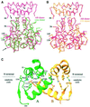
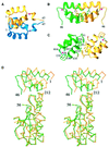
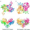
Retroviral integrase, an essential enzyme for replication of human immunodeficiency virus type-1 (HIV-1) and other retroviruses, contains three structurally distinct domains, an N-terminal domain, the catalytic core and a C-terminal domain. To elucidate their spatial arrangement, we have solved the structure of a fragment of HIV-1 integrase comprising the N-terminal and catalytic core domains. This structure reveals a dimer interface between the N-terminal domains different from that observed for the isolated domain. It also complements the previously determined structure of the C-terminal two domains of HIV-1 integrase; superposition of the conserved catalytic core of the two structures results in a plausible full-length integrase dimer. Furthermore, an integrase tetramer formed by crystal lattice contacts bears structural resemblance to a related bacterial transposase, Tn5, and exhibits positively charged channels suitable for DNA binding.
Figures


Similar articles
-
Crystal structure of the HIV-1 integrase catalytic core and C-terminal domains: a model for viral DNA binding.Proc Natl Acad Sci U S A. 2000 Jul 18;97(15):8233-8. doi: 10.1073/pnas.150220297. Proc Natl Acad Sci U S A. 2000. PMID: 10890912 Free PMC article.
-
Structural and dynamical properties of a full-length HIV-1 integrase: molecular dynamics simulations.J Biomol Struct Dyn. 2006 Jun;23(6):613-24. doi: 10.1080/07391102.2006.10507086. J Biomol Struct Dyn. 2006. PMID: 16615807
-
The conformational feasibility for the formation of reaching dimer in ASV and HIV integrase: a molecular dynamics study.J Biomol Struct Dyn. 2017 Dec;35(16):3469-3485. doi: 10.1080/07391102.2016.1257955. Epub 2016 Nov 28. J Biomol Struct Dyn. 2017. PMID: 27835934 Free PMC article.
-
HIV integrase structure and function.Adv Virus Res. 1999;52:319-33. doi: 10.1016/s0065-3527(08)60304-8. Adv Virus Res. 1999. PMID: 10384240 Review.
-
HIV-1 integrase: structural organization, conformational changes, and catalysis.Adv Virus Res. 1999;52:351-69. doi: 10.1016/s0065-3527(08)60306-1. Adv Virus Res. 1999. PMID: 10384242 Review.
Cited by
-
Dialysis purification of integrase-DNA complexes provides high-resolution atomic force microscopy images: dimeric recombinant HIV-1 integrase binding and specific looping on DNA.PLoS One. 2013;8(1):e53572. doi: 10.1371/journal.pone.0053572. Epub 2013 Jan 14. PLoS One. 2013. PMID: 23341952 Free PMC article.
-
Classification and Design of HIV-1 Integrase Inhibitors Based on Machine Learning.Comput Math Methods Med. 2021 Apr 1;2021:5559338. doi: 10.1155/2021/5559338. eCollection 2021. Comput Math Methods Med. 2021. PMID: 33868450 Free PMC article.
-
Cis-Allosteric Regulation of HIV-1 Reverse Transcriptase by Integrase.Viruses. 2022 Dec 21;15(1):31. doi: 10.3390/v15010031. Viruses. 2022. PMID: 36680070 Free PMC article.
-
Biochemical and virological analysis of the 18-residue C-terminal tail of HIV-1 integrase.Retrovirology. 2009 Oct 19;6:94. doi: 10.1186/1742-4690-6-94. Retrovirology. 2009. PMID: 19840380 Free PMC article.
-
Analysis of the contribution of reverse transcriptase and integrase proteins to retroviral RNA dimer conformation.J Virol. 2005 May;79(10):6338-48. doi: 10.1128/JVI.79.10.6338-6348.2005. J Virol. 2005. PMID: 15858017 Free PMC article.
References
-
- Aldaz H., Schuster,E. and Baker,T.A. (1996) The interwoven architecture of the Mu transposase couples DNA synapsis to catalysis. Cell, 85, 257–269. - PubMed
-
- Asante-Appiah E. and Skalka,A.M. (1997) Molecular mechanisms in retrovirus DNA integration. Antiviral Res., 36, 139–156. - PubMed
-
- Brown P.O. (1997) Integration. In Coffin,J.M., Hughes,S.H. and Varmus,H.E. (eds), Retroviruses. Cold Spring Harbor Laboratory Press, Cold Spring Harbor, NY, pp. 161–203.
-
- Brünger A.T. et al. (1998) Crystallography and NMR system: a new software suite for macromolecular structure determination. Acta Crystallogr. D, 54, 905–921. - PubMed
Publication types
MeSH terms
Substances
Associated data
- Actions
LinkOut - more resources
Full Text Sources
Other Literature Sources

