. 2002 Mar;87(3):205-9.
doi: 10.1136/heart.87.3.205.

Virtual coronary angioscopy using multislice computed tomography

Affiliations

Virtual coronary angioscopy using multislice computed tomography

S Schroeder et al. Heart. 2002 Mar.

Abstract

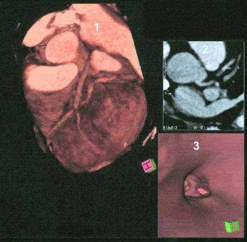
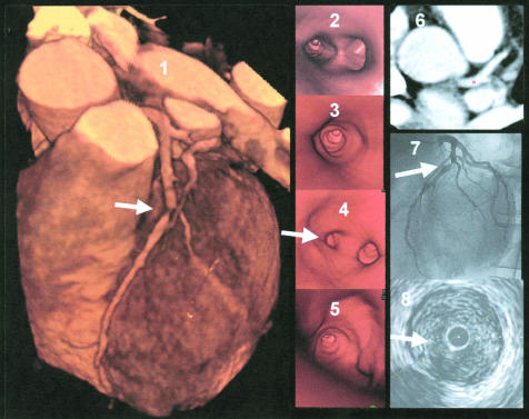
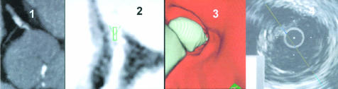
Background: With faster image acquisition times and thinner slice widths, multislice detector computed tomography (MSCT) allows visualisation of human coronary arteries with diagnostic image quality. In addition to conventional axial slices, virtual coronary angioscopies (VCA) can be reconstructed using MSCT datasets.

Objective: To evaluate the feasibility of reconstructing VCA and to determine the clinical value of this new application in detecting atherosclerotic coronary artery lesions.

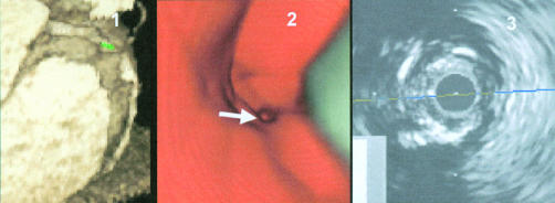
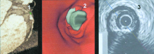
Methods: Datasets obtained by contrast enhanced non-invasive coronary angiography using MSCT (Somatom VZ) were analysed from 14 consecutive patients. VCA were simulated in 14 coronary arteries (left anterior descending, n = 7; right coronary, n = 7). Lesion detection was undertaken on conventional contrast enhanced axial slices, as well as by VCA. Intracoronary ultrasound (ICUS) was used as the gold standard for in vivo plaque detection.

Results: 38 lesions were detected both on ICUS and on axial slices: 14 severe target lesions of > 75% area stenosis (11 calcified, three non-calcified), and 24 intermediate lesions of < or = 75% area stenosis (seven calcified, 17 non-calcified). Using VCA, all severe lesions (n = 14) and all calcified intermediate plaques (n = 7) could clearly be identified. However, non-calcified intermediate lesions (n = 17) could not be accurately distinguished from the vessel wall; they were recognised as vessel wall alterations without significant luminal narrowing.

Conclusions: Current MSCT technology allows reconstruction of VCA with good image quality. Despite a more anatomical view of heart and coronary vessels on three dimensional reconstruction, conventional axial slices were found to be superior for detecting coronary lesions. Thus further technical innovations are required before VCA can become a useful technique in clinical cardiology.


Figures

Figure 1
Figure 1
Volume rendering controls with a histogram showing voxel density values. The x axis shows the voxel values, the y axis the frequency distribution. The first peak represents air, the second fat, the third tissue, and the fourth contrast medium (CM). The orange graph represents the range used for visualising vessel, the white graph represents the range used for visualising calcification.
Figure 2
Figure 2
Simultaneous display of three dimensional volume rendering image, axial slice image, and virtual coronary angioscopy. Panel 1: three dimensional volume rendering images showing left anterior descending coronary artery (LAD) with severe stenosis. Panel 2: axial slice image. Panel 3: virtual coronary angioscopy, showing the left main stem and the bifurcation of LAD/left circumflex coronary artery.
Figure 3
Figure 3
Visualisation of a non-calcified atherosclerotic coronary lesion on conventional contrast enhanced axial slices. Left: contrast enhanced conventional axial slice visualising two non-calcified plaques. Right: corresponding intracoronary ultrasound image (longitudinal scan). Ao, aorta; LAD, left anterior descending coronary artery; LMS, left main stem; PT, pulmonary trunk.
Figure 4
Figure 4
Example of an image from a patient with severe stenosis in the left anterior descending coronary artery. Panel 1: three dimensional volume rendering image, showing a severe lesion in the left anterior descending coronary artery (LAD, marked with an arrow). Panel 2: endoscopic view into the left main stem with visualisation of the LAD/left circumflex coronary artery bifurcation. Panel 3: proximal segment of LAD with vessel wall alterations but non-significant luminal narrowing. Panel 4: view at the severe lesion (on the left) and origin of the diagonal branch (on the right). Panel 5: view from inside the severe lesion into the vessel periphery of the LAD. Panel 6: axial slice image with navigator located in the left main stem. Panel 7: corresponding coronary angiography image, showing the severe LAD lesion. Panel 8: intracoronary ultrasound image within the severe non-calcified lesion.
Figure 5
Figure 5
Severe calcifications in the proximal segment in the right coronary artery (RCA). Panel 1: axial view of the proximal segments of the RCA. Panel 2: multiplanar reformatted (MPR) view with navigator, segmented calcification. Panel 3: virtual coronary angioscopy of the corresponding segment with visualisation of the segmentation. Panel 4: corresponding intracoronary ultrasound image with calcification but without severe stenosis.
Figure 6
Figure 6
Severe lesion in segment 2 of the right coronary artery. Panel 1: three dimensional volume rendering image of the right coronary artery with severe lesion and calcifications—the navigator is positioned in front of the lesion. Panel 2: virtual coronary angioscopy of the corresponding segment, visualising the severe lesion with calcification. Panel 3: intracoronary ultrasound image of the corresponding segment, visualising the severe stenosis and calcifications.
Figure 7
Figure 7
Example of an image from a patient with severe calcifications and a severe stenosis in the right coronary artery. Panel 1: three dimensional volume rendering image of the right coronary artery with high grade stenosis and calcifications—the navigator is positioned immediately beyond the stenosis. Panel 2: virtual coronary angioscopy view into the distal reference segment with “free floating” calcification in front of the lesion. Panel 3: intracoronary ultrasound image of the corresponding segment, visualising a calcified lesion.

Comment in

Similar articles

Cited by

References

    1. Ackerman JD. Medicine meets virtual reality 2000. MD Comput 2000;17:13–17. - PubMed
    1. Fletcher JG, Luboldt W. CT colonography and MR colonography: current status, research directions and comparison. Eur Radiol 2000;10:786–801. - PubMed
    1. Potchen EJ. Prospects for progress in diagnostic imaging. J Intern Med 2000;247:411–24. - PubMed
    1. Ott DJ. Virtual gastroscopy: a new look at the stomach. Am J Gastroenterol 2000;95:1084–5. - PubMed
    1. Chaoui AS, Blake MA, Barish MA, et al. Virtual colonoscopy and colorectal cancer screening. Abdom Imaging 2000;25:361–7. - PubMed