

Verification of dynamic and segmental IMRT delivery by dynamic log file analysis
- PMID: 11958647
- PMCID: PMC5724614
- DOI: 10.1120/jacmp.v3i2.2578
Verification of dynamic and segmental IMRT delivery by dynamic log file analysis
Abstract
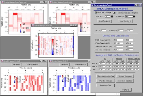
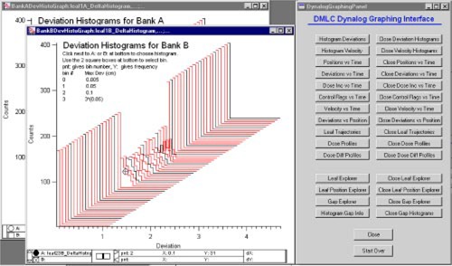
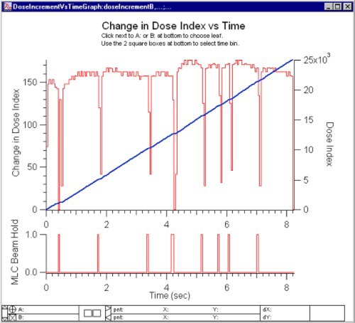
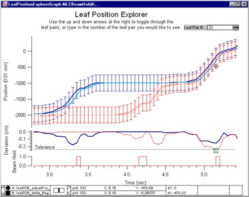
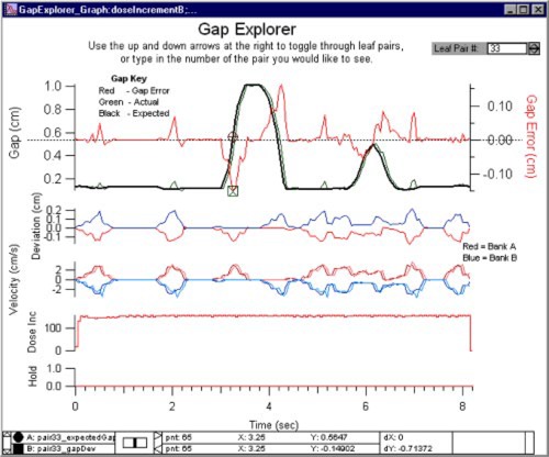
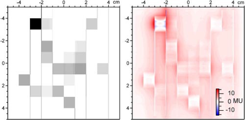
A program has been developed to evaluate the delivered fluence of step-and-shoot segmental and sliding window dynamic multileaf collimator (MLC) fields. To automate these checks, a number of tools have been developed using data available from the dynamic log files that can be created each time a dynamic delivery occurs. Experiments were performed with a Varian 2100EX with a 120 leaf MLC equipped with dynamic capabilities. A dynamic leaf sequence is delivered and measured with film or an amorphous silicon imager. After delivery, the dynamic log file is written by the accelerator control system. The file reports the expected and actual position for each leaf and the dose fraction every 0.055 seconds. Leaf trajectories are calculated from this data and expected and actual fluence images are created from the difference of opposing leaf trajectories. These images can be compared with the expected delivery, measurements, and calculations of fluence. Tools have been developed to investigate other aspects of the delivery, such as specific leaf errors, beam hold-off flags sent by the control system to the MLC, and gap widths. This program is part of a semi-automated quality assurance (QA) system for pretreatment fluence verification and daily treatment verification of dynamic multileaf collimation (DMLC) delivery.
Figures
References
-
- Ma L., Geis P. B., and Boyer AL., “Quality assurance for dynamic multileaf collimator modulated fields using a fast beam imaging system,” Med. Phys. 24, 1213–1220 (1997). - PubMed
-
- Patridge M., Evans P. M., Mosleh‐Shirazi A., and Convery D., “Independent verification of intensity‐modulated beam delivery by the dynamic MLC technique,” Med. Phys. 25, 1872–1879 (1998). - PubMed
-
- Pasma K. L., Kroonwijk M., de Boer J. C., Visser A. G., and Heijmen B. J., “Accurate portal dose measurement with a fluoroscopic electron portal imaging device (EPID) for open and wedged beams and dynamic multileaf collimation,” Phys. Med. Biol. 43, 2047–2060 (1998). - PubMed
-
- James H. V., Atherton S., Budgell G. J., Kirby M. C., and Williams P. C., “Verification of dynamic multileaf collimation using an electronic portal imaging device,” Phys. Med. Biol. 45 (2), 495–509 (2000). - PubMed
-
- Papatheodorou S., Rosenwald J. C., Zefkili S., Murillo M. C., Drouard J., and Gaboriaud G., “Dose calculation and verification of intensity modulation generated by dynamic multileaf collimators,” Med. Phys. 27 (5), 960–971 (2000). - PubMed
Publication types
MeSH terms
Grants and funding
LinkOut - more resources
Full Text Sources
Miscellaneous
