. 2002 May 1;21(9):2242-52.
doi: 10.1093/emboj/21.9.2242.

Structural basis of VDR-DNA interactions on direct repeat response elements

Affiliations

Structural basis of VDR-DNA interactions on direct repeat response elements

Paul L Shaffer et al. EMBO J. .

Abstract

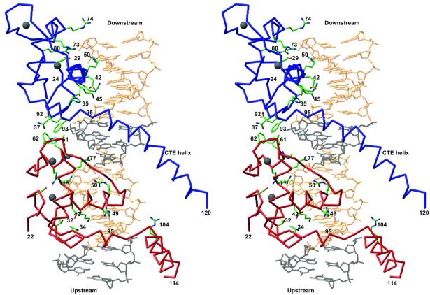
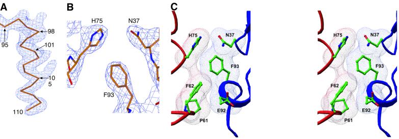
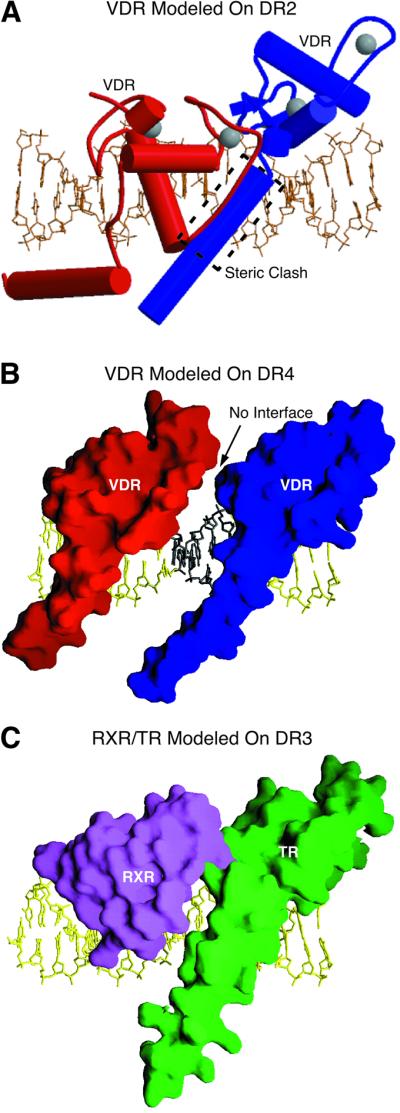
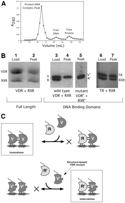
The vitamin D receptor (VDR) forms homo- or heterodimers on response elements composed of two hexameric half-sites separated by 3 bp of spacer DNA. We describe here the crystal structures at 2.7-2.8 A resolution of the VDR DNA-binding region (DBD) in complex with response elements from three different promoters: osteopontin (SPP), canonical DR3 and osteocalcin (OC). These structures reveal the chemical basis for the increased affinity of VDR for the SPP response element, and for the poor stability of the VDR-OC complex, relative to the canonical DR3 response element. The homodimeric protein-protein interface is stabilized by van der Waals interactions and is predominantly non-polar. An extensive alpha-helix at the C-terminal end of the VDR DBD resembles that found in the thyroid hormone receptor (TR), and suggests a mechanism by which VDR and TR discriminate among response elements. Selective structure-based mutations in the asymmetric homodimeric interface result in a VDR DBD protein that is defective in homodimerization but now forms heterodimers with the 9-cis retinoic acid receptor (RXR) DBD.


Figures

None
Fig. 1. Protein and DNA constructs used in the structure determination. (A) The human VDR DBD. Sequence numbers are for full-length hVDR and those in parentheses refer to the common hormone receptor DBD numbering scheme. Residues in italics are disordered in all of the structures. (B) The 18 bp DNA duplexes used in co-crystallization, shown 5′→3′ in the top strand. Half-sites are shown in boxes and are numbered by base pair. The DR3 sequence contains a direct repeat of two consensus half-sites. SPP is the mouse osteopontin VDRE and OC is the rat osteocalcin VDRE. Bases that differ from the consensus sequence are shaded gray and the structurally significant changes are highlighted in black. Estimates of relative binding of VDR DBD homodimers to each sequence are also shown.
None
Fig. 2. Overall architecture of the VDR DBD–DR3 complex. The red and blue Cα traces are the upstream and downstream subunits, respectively. Selected side chains are shown in green. Gray spheres are Zn atoms. The canonical half-site sequence is shown in gold, and the 5′-flanking base pairs and the spacer are shown in black. The structures of all three complexes presented here have the same overall architecture. The figure was made with Ribbons (Carson, 1991).
None
Fig. 3. Experimental electron density and homodimeric assembly. (A) Unbiased experimental electron density from SAD phases. The map is contoured around the CTE of the upstream subunit of the VDR DBD–DR3 structure, which is shown as a Cα trace. (B) A portion of the 2Fo = Fc electron density map showing intersubunit dimerization contacts. (C) Stereo view of the dimerization interface in a van der Waals surface representation. (A) and (B) were made with Xtalview (McRee, 1999), and (C) was prepared with Ribbons.
None
Fig. 4. The VDR CTE resembles that of TR and is present in solution. (A) Superimposition of VDR, TR and RevErb DBDs. Proteins were aligned using the recognition helix and half-site DNA. The residue at the end of the core region (Met89) is marked, as is the position of Asp97 of VDR and the position of RevErb that would correspond to residue 97. (B) Circular dichroism of free and complexed VDR DBD.
None
Fig. 5. Modeling studies based on VDR DBD structure. (A) Model of the VDR homodimer bound to a DR2 element. A likely steric clash is boxed. This figure was made with Molscript (Kraulis, 1991). (B) Model of the VDR homodimer bound to a DR4 element. Molecular surfaces of the proteins are shown. (C) Model of the RXR–TR heterodimer bound to DR3 DNA from the VDR homodimer structure. Proteins were placed by superimposing the backbone atoms of the core DBD and DNA half-site. (B) and (C) were prepared with GRASP (Nicholls et al., 1991).
None
Fig. 6. Protein–DNA contacts observed in the three response elements. (A) Base-specific contacts. The DNA is drawn underwound for clarity only. Hydrogen bonds are depicted as arrows, with the donor at the tail of the arrow. Dashed lines represent hydrogen bonds seen in only one of the two half-site complexes. If a side chain has more than one functional group, arrows contacting the same region on an oval arise from the same group. (B) Backbone contacts common to at least five of six half-sites. Dotted lines are interactions seen only in the upstream half-complex. (C) Details of the Glu42 and Arg50 hydrogen bonds in selected complexes showing key specifying interactions.
None
Fig. 7. Structure-based mutations and RXR–VDR DBD heterodimer formation. (A) A typical chromatogram showing isolation of dimeric DBD–DNA complexes on Superdex 75. (B) SDS–PAGE analysis of proteins in the complex peak. The lanes labeled ‘Load’ show the actual mixture of proteins applied to the column, and those labeled ‘Peak’ show the composition of the peak fraction of the protein–DNA complex peak. With full-length VDR–RXRΔAB–DR3 and RXR DBD–TR DBD–DR4, both proteins are recovered (lanes 2 and 7), indicating heterodimerization. With wild-type VDR and RXR DBD (lane 4), no RXR is observed. Since the protein:DNA ratio of the peak was determined to be 2:1, this indicates that only VDR homodimers are formed. In contrast, lane 5 shows that the mutant VDR and RXR DBDs form heterodimers since both proteins are recovered in the peak fraction. (C) Rationale behind structure-based mutations of VDR and RXR DBDs. Wild-type VDR and RXR DBDs are labeled V and R, mutant proteins are labeled V′ and R′, and half-site DNA is represented as an arrow. The favored dimeric species are boxed and the disfavored assembly pathway is indicated with an X.

References

    1. Abe E., Miyaura,C., Sakagami,H., Takeda,M., Konno,K., Yamazaki,T., Yoshiki,S. and Suda,T. (1981) Differentiation of mouse myeloid leukemia cells induced by 1 α,25-dihydroxyvitamin D3. Proc. Natl Acad. Sci. USA, 78, 4990–4994. - PMC - PubMed
    1. Baker A.R., McDonnell,D.P., Hughes,M., Crisp,T.M., Mangelsdorf, D.J., Haussler,M.R., Pike,J.W., Shine,J. and O’Malley,B.W. (1988) Cloning and expression of full-length cDNA encoding human vitamin D receptor. Proc. Natl Acad. Sci. USA, 85, 3294–3298. - PMC - PubMed
    1. Bouillon R., Okamura,W.H. and Norman,A.W. (1995) Structure–function relationships in the vitamin D endocrine system. Endocr. Rev., 16, 200–257. - PubMed
    1. Brünger A.T. et al. (1998) Crystallography and NMR system: a new software suite for macromolecular structure determination. Acta Crystallogr., D54, 905–921. - PubMed
    1. Carson M. (1991) Ribbons 2.0. J. Appl. Crystallogr., 24, 958–961.

MeSH terms