. 2002 Aug;120(2):159-72.
doi: 10.1085/jgp.20018536.

Effect of Na(+) flow on Cd(2+) block of tetrodotoxin-resistant Na(+) channels

Affiliations

Effect of Na(+) flow on Cd(2+) block of tetrodotoxin-resistant Na(+) channels

Chung-Chin Kuo et al. J Gen Physiol. 2002 Aug.

Abstract

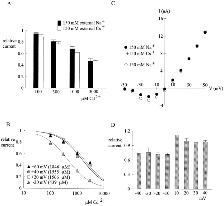
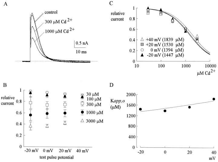
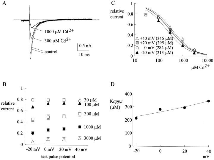
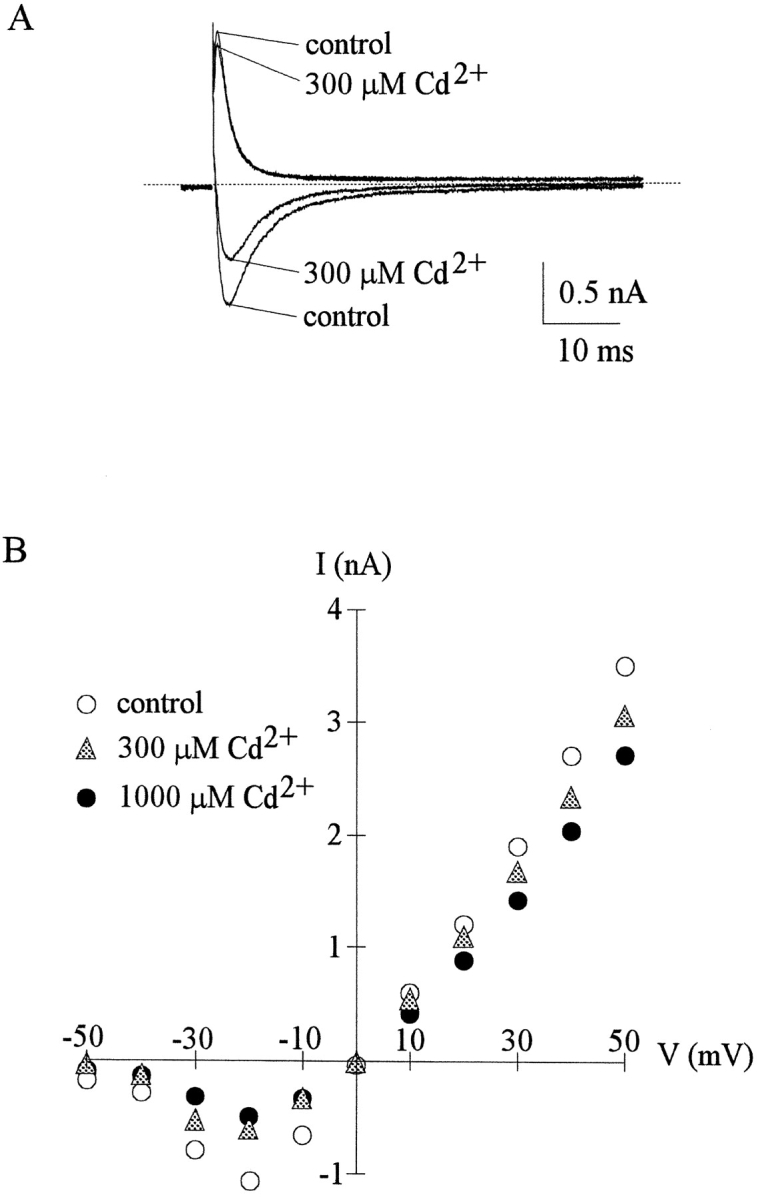
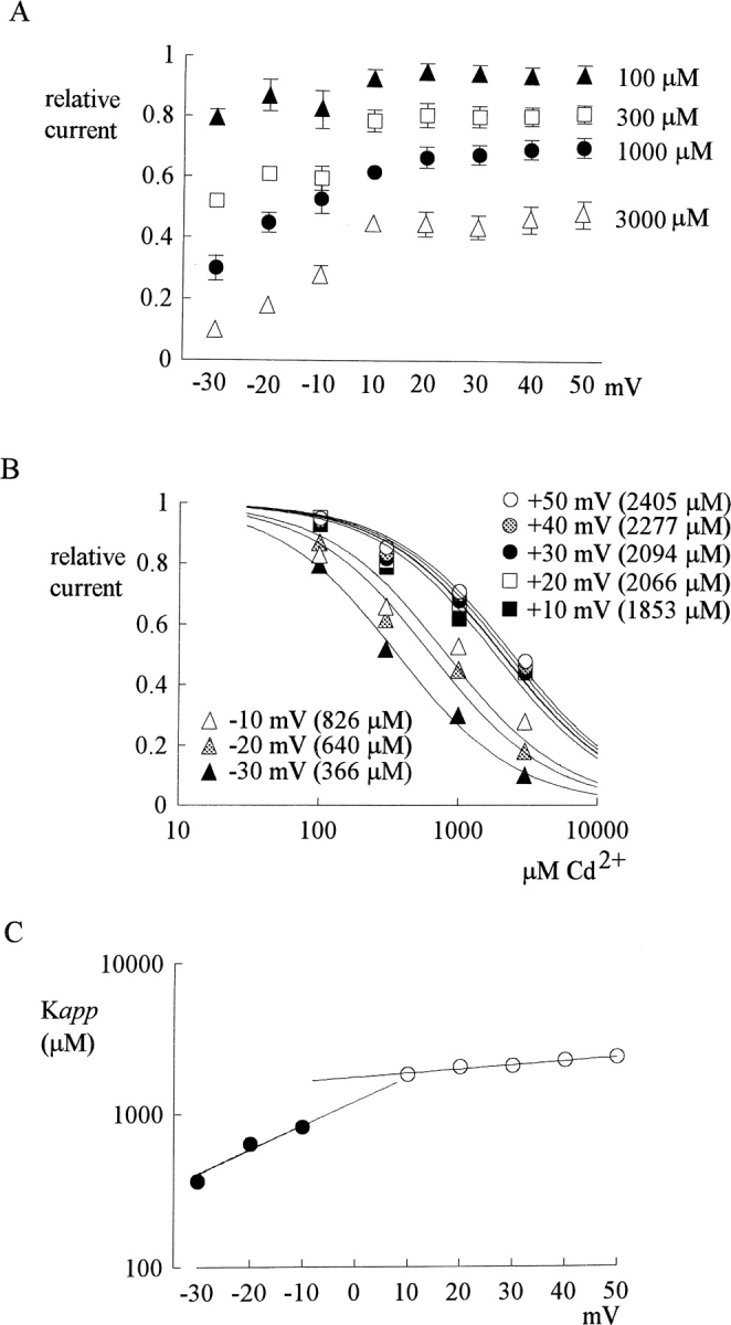
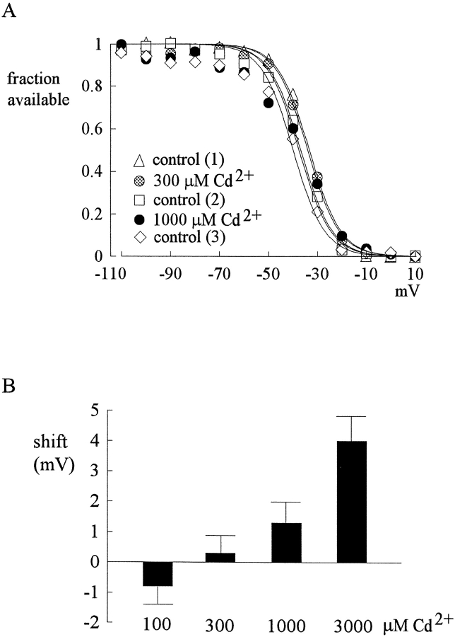
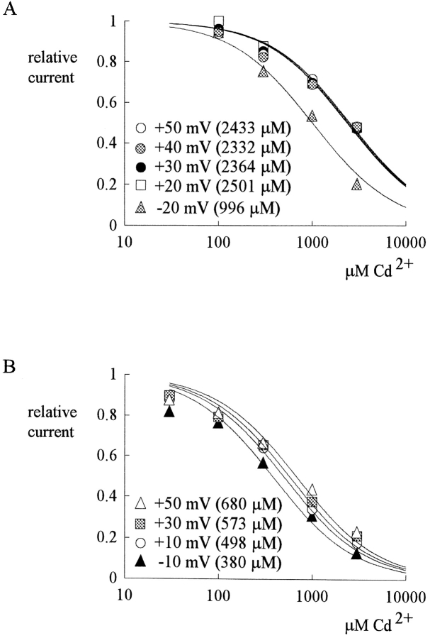
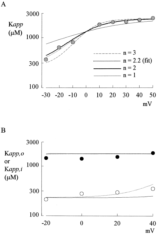
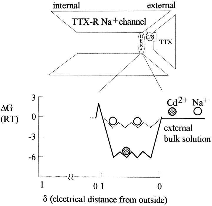
Tetrodotoxin-resistant (TTX-R) Na(+) channels are 1,000-fold less sensitive to TTX than TTX-sensitive (TTX-S) Na(+) channels. On the other hand, TTX-R channels are much more susceptible to external Cd(2+) block than TTX-S channels. A cysteine (or serine) residue situated just next to the aspartate residue of the presumable selectivity filter "DEKA" ring of the TTX-R channel has been identified as the key ligand determining the binding affinity of both TTX and Cd(2+). In this study we demonstrate that the binding affinity of Cd(2+) to the TTX-R channels in neurons from dorsal root ganglia has little intrinsic voltage dependence, but is significantly influenced by the direction of Na(+) current flow. In the presence of inward Na(+) current, the apparent dissociation constant of Cd(2+) ( approximately 200 microM) is approximately 9 times smaller than that in the presence of outward Na(+) current. The Na(+) flow-dependent binding affinity change of Cd(2+) block is true no matter whether the direction of Na(+) current is secured by asymmetrical chemical gradient (e.g., 150 mM Na(+) vs. 150 mM Cs(+) on different sides of the membrane, 0 mV) or by asymmetrical electrical gradient (e.g., 150 mM Na(+) on both sides of the membrane, -20 mV vs. 20 mV). These findings suggest that Cd(2+) is a pore blocker of TTX-R channels with its binding site located in a multiion, single-file region near the external pore mouth. Quantitative analysis of the flow dependence with the flux-coupling equation reveals that at least two Na(+) ions coexist with the blocking Cd(2+) ion in this pore region in the presence of 150 mM ambient Na(+). Thus, the selectivity filter of the TTX-R Na(+) channels in dorsal root ganglion neurons might be located in or close to a multiion single-file pore segment connected externally to a wide vestibule, a molecular feature probably shared by other voltage-gated cationic channels, such as some Ca(2+) and K(+) channels.


Figures

F<sc>igure</sc> 5.
Figure 5.
The effect of external Na+ and Cs+ on Cd2+ block. (A) The relative currents in the presence of 100–3,000 μM Cd2+ at 40 mV (data from part of Figs. 1 B and 4 A) are replotted here for a better comparison. Because in either case the membrane is strongly depolarized and the internal solution contains 150 mM Na+, the Na+ current is always outward no matter the external solution contains 150 mM Cs+ (white bar, n = 4–7) or 150 mM Na+ (black bar, n = 5–7). There is no definite difference in the inhibitory effect of Cd2+ between the two cases. (B) In symmetrical 150 mM Na+ + 150 mM Cs+, the blocking effect of Cd2+ on inward (−20 mV) and outward (20–60 mV) currents is assessed in a way similar to that in Fig. 4 B. The error bars of the mean relative currents are in general <10% of the mean values and are omitted for clarity (n = 2–9). The lines are best fits for each set of data of the form: relative current = 1/{1 + ([Cd2+]/K app,Cs)}, where K app,Cs stands for the apparent dissociation constant of external Cd2+ when both outward and inward Na+ currents are elicited with symmetrical 150 mM Na+ + 150 mM Cs+ on both sides of the membrane. The K app,Cs from the fits are given in the parentheses in the figure. (C) Similar to the I-V plot in Fig. 3 B, in a dorsal root ganglion neuron the peak inward and outward Na+ currents were recorded in 150 mM external Na+ solution and in 150 mM Na+ + 150 mM Cs+ external solution, respectively, and are plotted against the test pulse voltage. Note that the inhibition of inward currents by the addition of 150 mM external Cs+ is evident, whereas the outward currents are essentially unaffected. Also note that the I-V plots are of very similar shape whether Cs+ is present or not. (D) The relative currents at each different test pulse voltages is defined as the ratio between the peak currents in the presence and absence of 150 mM Cs+ in the experiments in C (n = 4). The inhibition produced by Cs+ is similar in all inward currents (−10 to −40 mV), whereas the outward currents are clearly unaffected by Cs+.
F<sc>igure</sc> 1.
Figure 1.
Outward TTX-R Na+ currents inhibited by external Cd2+. (A) The cell was held at −130 mV and stepped every 4 s to the test pulse (0 mV) for 60 ms. With 150 mM Na+ internal solution and 150 mM Cs+ external solution, outward TTX-R Na+ currents were elicited by depolarization to 0 mV and were inhibited by 300 and 1,000 μM Cd2+. The two control sweeps were obtained before and after Cd2+ inhibition, demonstrating rapid reversibility of the inhibition. The dotted line indicates the zero current level. (B) Inhibition of outward TTX-R Na+ currents by different concentrations (30–3,000 μM, as indicated beside each series of symbols) of Cd2+ at different test pulse voltages. The experimental conditions and pulse protocols were generally similar to that described in A, except that the test pulse was varied from −20 to 40 mV in 20-mV steps (the horizontal axis). The relative current (the vertical axis) at each test pulse potential is defined by normalization of the peak currents in the presence of Cd2+ to the peak current in the control (Cd2+-free) solution (n = 3–9). The inhibition is clearly Cd2+ concentration dependent, yet shows only minimal voltage dependence. (C) The mean relative current in B is plotted against [Cd2+] (the concentration of Cd2+) in semilogarithmic scale. The lines are best fits for each set of data points of the form: relative current = 1/{1 + ([Cd2+]/K app,o)}, where K app,o stands for the apparent dissociation constant of Cd2+ in such an experimental configuration (150 mM Cs+ outside and outward Na+ current). The K app,o from the fits are given in the parentheses in the figure. (D) The K app,o obtained in C are plotted against test pulse voltage in semilogarithmic scale. The line is the best fit to the data points of the form: K app,o = 1480 μM * exp(V/230), where V stands for the test pulse voltage in mV.
F<sc>igure</sc> 2.
Figure 2.
Inward TTX-R Na+ currents inhibited by external Cd2+. (A) The pulse protocol was essentially the same as that described in the legend to Fig. 1 A. With 150 mM Cs+ internal solution and 150 mM Na+ external solution, inward TTX-R Na+ currents were elicited by depolarization to 0 mV and were inhibited by 300 and 1,000 μM Cd2+. Once more, the two control sweeps were obtained before and after Cd2+ inhibition, demonstrating rapid reversibility of the inhibition. The dotted line indicates the zero current level. (B) Inhibition of inward TTX-R Na+ currents by different concentrations (30–3,000 μM, as indicated beside each series of symbols) of Cd2+ at different test potentials. The pulse protocols and the definition of relative current were the same as those in Fig. 1 B (n = 4–12). Again, the inhibition is dependent on Cd2+ concentration yet shows only very small voltage dependence. (C) The mean relative current in B is plotted against [Cd2+] (the concentration of Cd2+) in semilogarithmic scale. The lines are best fits for each set of data points of the form: relative current = 1/{1 + ([Cd2+]/K app,i)}, where K app,i stands for the apparent dissociation constant of Cd2+ in such an experimental condition (150 mM Cs+ inside and inward Na+ current). The K app,i from the fits are given in the parentheses in the figure. (D) The K app,i obtained in C are plotted against test pulse voltage in semilogarithmic scale. The line is the best fit to the data points of the form: K app,i = 260 μM * exp(V/140), where V stands for the test pulse voltage in mV.
F<sc>igure</sc> 3.
Figure 3.
Outward and inward TTX-R currents inhibited by external Cd2+. (A) The cell was held at −130 mV and stepped every 4 s to the test pulse at −20 or 20 mV for 60 ms. With equimolar Na+ on both sides of the membrane (150 mM Na+ internal solution and 150 mM Na+ external solution), outward TTX-R Na+ currents were elicited by depolarization to 20 mV and inward TTX-R Na+ currents were elicited by depolarization to −20 mV. The inhibitory effect of 300 μM external Cd2+ is obviously stronger on the inward current than on the outward current. The dotted line indicates the zero current level. (B) In the same cell as that in A, the peak inward and outward Na+ currents were recorded in the control solution and in the presence of 300–1,000 μM Cd2+, and are plotted against the test pulse voltage. For all inward and outward Na+ currents elicited by test pulse of different voltages, the inhibition produced by Cd2+ remains similar for the same direction of current flow, but inhibition of inward currents is always much more manifest than inhibition of outward currents. Note that the current-voltage plots are of very similar shape whether Cd2+ is present or not (e.g., the currents all start to be discernible at the currents at −50 mV, the peak inward currents all appear at −20 mV, and the currents all reverse at ∼0 mV). The similar I-V relationship strongly argues against significant effect of 300–1,000 μM Cd2+ on the surface potential related to channel gating. Also, the almost linear I-V relationship beyond −20 mV further discloses that channel activation is nearly complete at membrane potentials more positive than −20 mV.
F<sc>igure</sc> 4.
Figure 4.
Inhibition of outward and inward TTX-R Na+ currents by different concentrations (100–3,000 μM) of Cd2+ at different test potentials with equimolar (150 mM) Na+ on both sides of the membrane (the same internal and external solutions as those in Fig. 3). (A) The pulse protocols were generally similar to that described in Fig. 1A, except that the test pulse was varied from −30 to 50 mV in 10-mV steps (the horizontal axis). The definition of relative current (the vertical axis) is also the same as that in Fig. 1 A (n = 3–7). The inhibitory effect is Cd2+ concentration dependent, and is more manifest on the inward currents than on the outward currents for every Cd2+ concentration tested. Also, the inhibition shows little voltage dependence when there is outward current, yet shows stronger apparent voltage dependence when there is inward current. (B) Dissociation constants of Cd2+ to the TTX-R channels in the presence of outward or inward Na+ current in symmetrical (150 mM) Na+. The mean relative current in A is plotted against [Cd2+] (the concentration of Cd2+) in semilogarithmic scale. The lines are best fits for each set of data of the form: relative current = 1/{1 + ([Cd2+]/K app)}, where K app stands for the apparent dissociation constant of external Cd2+ when either outward or inward Na+ currents are elicited with symmetrical 150 mM Na+ on both sides of the membrane. The K app from the fits are given in the parentheses in the figure. We did not measure the K app below −30 mV where TTX-R channels are probably far from fully activated (judged from, for example, the I-V plot in Fig. 3 B). Thus, a slight change in surface potential might have a significant effect on channel activation and consequently the amplitude of the current in these negative potentials. (C) The K app obtained in B are plotted against test pulse voltage in semilogarithmic scale. The top line is the best fit to the data points in inward Na+ currents (at test pulses −30 to −10 mV) and is of the form: K app = 1220 μM * exp(V/27), where V stands for the test pulse voltage in mV. The bottom line is the best fit to the data points in outward currents (at test pulses 10–50 mV) and is of the form: K app = 1770 μM * exp(V/165), where V stands for the test pulse voltage in mV. The two fitting lines, however, are obviously discontinuous functions.
F<sc>igure</sc> 6.
Figure 6.
Insignificant surface potential changes produced by Cd2+. (A) The surface potential changes caused by Cd2+ is examined by shift of the inactivation curve of TTX-R channels. The cell was held at −120 mV and stepped every 2 s to the inactivating pulse (−120 to 10 mV) for 100 ms. The channels which remain available after each inactivating pulse were assessed by the peak currents during the following short test pulse at 40 mV for 20 ms. The fraction available is defined as the normalized peak current (relative to the current evoked with an inactivating pulse at −120 mV) and is plotted against the voltage of the inactivating pulse. Three sets of control data were obtained before, between, and after the two sets of data in 300 and 1,000 μM Cd2+. The lines are fits with a Boltzmann function 1/{1 + exp[(V − Vh)/6.5]}, with Vh values (in mV) of −33.7, −34.1, −36.9, −37.4, and −39.8 for control (1, before Cd2+), 300 μM Cd2+, control (2, between 300 and 1000 μM Cd2+), 1,000 μM Cd2+, and control (3, after 1,000 μM Cd2+), respectively. (B) The shift of inactivation curves assessed by the difference of Vh values in control and in 100–3,000 μM Cd2+. The shift is insignificant with lower concentrations of Cd2+ and is ∼1.5 and ∼4 mV for 1,000 and 3,000 μM Cd2+ (n = 3–4), respectively.
F<sc>igure</sc> 7.
Figure 7.
The effect of high (5 mM) external Ca2+ on Cd2+ block. (A) In symmetrical 150 mM Na+ with 5 mM Ca2+ present in the external solution, the blocking effect of Cd2+ on TTX-R currents is assessed in a way similar to that in Fig. 4 B (n = 2–9). The error bars of the mean relative currents are in general <10% of the mean values and are omitted for clarity. The lines are best fits for each set of data of the form: relative current = 1/{1 + ([Cd2+]/K app,Ca)}, where K app,Ca stands for the apparent dissociation constant of external Cd2+ when both outward and inward Na+ currents are elicited with symmetrical 150 mM Na+ and 5 mM external Ca2+. The K app,Ca from the fits are given in the parentheses in the figure. (B) With 150 mM Na+ and 5 mM Ca2+ present in the external solution and 150 mM Cs+ in the internal solution, the blocking effect of Cd2+ on TTX-R currents is assessed in a way similar to that in Fig. 2 C (n = 3–8). The error bars of the mean relative currents are in general smaller than 10% of the mean values and are omitted for clarity. The lines are best fits for each set of data of the form: relative current = 1/{1 + ([Cd2+]/K app,Cai)}, where K app,Cai stands for the apparent dissociation constant of external Cd2+ when inward Na+ currents are elicited with 150 mM Na+ and 5 mM Ca2+ in the external solution and 150 mM Cs+ in the internal solution. The K app,Cai from the fits are given in the parentheses in the figure.
F<sc>igure</sc> 8.
Figure 8.
Analysis of the experimental data with flux-coupling equations. (A) The data in Fig. 4 C are analyzed with Eq. 5 (see text). The thick dotted line is the best fit to the data of the form: K app = 2,400 μM * {exp(2.2V/25)/[1+exp(2.2V/25)]} + 260 μM * [1/exp(2.2V/25)], where V stands for the test pulse voltage in mV. The thin solid, thick solid, and thin dashed lines are curves with n values equal to 1, 2, and 3, respectively. It is evident that n = 1 describes the data much more poorly than n = 2 or 3. Because of limitation of the data range (the values below −30 mV cannot be reliably measured; Fig. 4B) and the simplifications made in the derivation of Eq. 5 (e.g., neglect of the small intrinsic voltage dependence of Cd2+ block), we do not mean to have an exact n, Do, and Di values from the fit. Instead, the major purpose is to show that the data described previously by two discontinuous functions considering only direct effect of the membrane electrical field on the blocking Cd2+ ion can actually be well described by one single equation based on the flux-coupling concepts. Also, it seems safe to say that more than 1, or at least 2, Na+ ions coexist with the blocking Cd2+ ion in this single-file region of the pore. (B) The same data points in Figs. 1 D (K app,o) and 2 D (K app,i) are put in the same plot and are described by an equation modified from Eqs. 1 and 5: D (K app,o or K app,i) = {R*exp(2V/25)/[1+R*exp(2V/25)]}*Do + {1/[1+R*exp(2V/25)]}*Di, where R equals to the square of the permeability ratio between Na+ and Cs+ (or between Cs+ and Na+, determined by the experimental configuration). For external Cs+ and internal Na+ (black symbols, the K app,o in Fig. 1 D), the R values are either 2,000 (solid line) or 200 (dashed line), and the Do and Di values are 1,800 and 200 μM, respectively. For internal Cs+ and external Na+ (white symbols, the K app,i in Fig. 2 D), as a first approximation R becomes inverses of the previous values and are either 0.0005 (solid line) or 0.005 (dashed line), whereas the Do and Di values are 2,100 and 230 μM, respectively. These Do and Di values are arbitrarily assigned to fit the data, because the apparent voltage dependence of the data points is simply too shallow to allow any purposeful fits. The slightly smaller Do and Di values than those in A probably partly reflecting the slightly enhanced Cd2+ binding rate because of the even weaker competition for the binding site by Cs+ than by Na+. The ∼9-fold difference between Do and Di, however, is deliberately kept unchanged. It is evident from the plot that the most important results from A (an ∼9-fold larger Do than Di, and an n value of ∼2–3) could also successfully describe the data in Figs. 1 and 2 over a wide range of permeability ratio between Na+ and Cs+.
F<sc>igure</sc> 9.
Figure 9.
A schematic diagram illustrating the major findings of this study. The cysteine or serine residue (a circle containing the letters C/S in the diagram) in the pore loop of domain I is the major ligand responsible for the poor binding affinity of TTX (mismatch of the shape of the binding counterparts). On the other hand, this residue, probably along with residues of the DEKA ring (equivalent to the EEEE ring in Ca2+ channels) and other unidentified residues, makes up a set of ion binding sites at the external pore mouth (electrical distance ∼0.05 from outside). It is a “set” of ion binding sites because the free energy of an ion (e.g., Na+) is roughly equal at any of these sites (although the absolute level of free energy may differ with different number or species of ions in the set), and these sites are not separated by any significant energy barriers for that particular ion. The ions therefore could move “freely” among these sites (if they are vacant), constituting the biophysical basis of flux-coupling effect. When one site is already occupied by an ion, presumably no other ion can pass the bound ion (single-file ionic flow), constituting the anatomical basis of flux-coupling effect. In the presence of 150 mM symmetrical Na+, there are probably at least two Na+ ions coexisting with the blocking Cd2+ ion in this multi-ion region. The TTX-R Na+ channel therefore should be able to accommodate at least three ions simultaneously. When there is essentially “strictly” outward Na+ current (Fig. 1 C or the right-end condition of the fitting curve in Fig. 8 A), unbinding of the blocking Cd2+ is almost always back to the external solution and as a first approximation the apparent dissociation constant of ∼1,839–2,400 μM in these situations may represent a “true” equilibrium constant. If the electrochemical zero free energy is set at 1 M ionic concentration, the ∼1,839–2,400 μM dissociation constant would be translated into a binding site with an energy well of ∼6 RT for Cd2+. On the other hand, the apparent dissociation constant of Cd2+ in “strictly” inward Na+ current is ∼9-fold smaller, or ∼213–260 μM (Fig. 2 C or the left-end condition of the fitting curve in Fig. 8 A). This is not a true equilibrium constant because Cd2+ comes from the outside yet exits to the inside. The energy barrier internal to the set of ionic sites thus must be ∼2.2 RT higher than the external energy barrier, making an ∼9-fold slower intrinsic inward exit rate and consequently an ∼9-fold smaller apparent dissociation constant. The peak of this internal energy barrier is separate from the Cd2+ binding by very small electrical dependence, because the dissociation constants in preponderant inward current show only minimal voltage dependence (Fig. 2 D). The free energy level of Na+ in the set is less clear, and is thus drawn with dotted lines. A rough estimate shows that these energy wells for Na+ should be much shallower than those for Cd2+, probably not deeper than ∼2 RT. This is because 150 mM external Na+ does not so significantly occupy all the sites as to prevent the entry of external Cd2+ to this pore region. It should be noted that the estimate of −2 RT applies to the situation that two Na+ ions already exist in this region. The first Na+ ion in this set of binding sites may enjoy an energy well deeper than −2 RT, and loading of subsequent Na+ ions is more and more difficult because of ion–ion repulsion. In other words, although we have focused on the flux-coupling effect, which explains the data reasonably well and may indeed be the major consequence of ion–ion interaction happening in this set of ionic sites, other subtle interactions such as ion–ion repulsion due to electrostatic repelling force or ligand competition could still exist in this multi-ion region and worth further exploration.

Similar articles

Cited by

References

    1. Akopian, A.N., L. Sivilotti, and J.N. Wood. 1996. A tetrodotoxin-resistant voltage-gated sodium channel expressed by sensory neurons. Nature. 379:257–262. - PubMed
    1. Akopian, A.N., V. Souslova, S. England, K. Okuse, N. Ogata, J. Ure, A. Smith, B.J. Kerr, S.B. McMahon, S. Boyce, et al. 1999. The tetrodotoxin-resistant sodium channel SNS has a specialized function in pain pathways. Nat. Neurosci. 2:541–548. - PubMed
    1. Backx, P.H., D.T. Yue, J.H. Lawrence, E. Marban, and G.F. Tomaselli. 1992. Molecular localization of an ion binding site within the pore of mammalian sodium channels. Science. 257:248–251. - PubMed
    1. Begenisich, T., and D. Busath. 1981. Sodium flux ratio in voltage-clamped squid giant axons. J. Gen. Physiol. 77:489–502. - PMC - PubMed
    1. Chandler, W.K., and H. Meves. 1965. Voltage-clamp experiments on internally perfused giant axons. J. Physiol. 180:821–836. - PMC - PubMed

Publication types