. 2002 Sep;23(8):1276-83.

Marker alignment for Guglielmi detachable coil embolization: practical considerations

Affiliations

Marker alignment for Guglielmi detachable coil embolization: practical considerations

O-Ki Kwon et al. AJNR Am J Neuroradiol. 2002 Sep.

Abstract

Background and purpose: Aneurysm embolization is not without risk: numerous technical aspects are considered before, during, and after the procedure. The purpose of this study was to show the position of the detachment zone of a Guglielmi detachable coil (GDC) with respect to the catheter tip for various microcatheters and marker alignments.

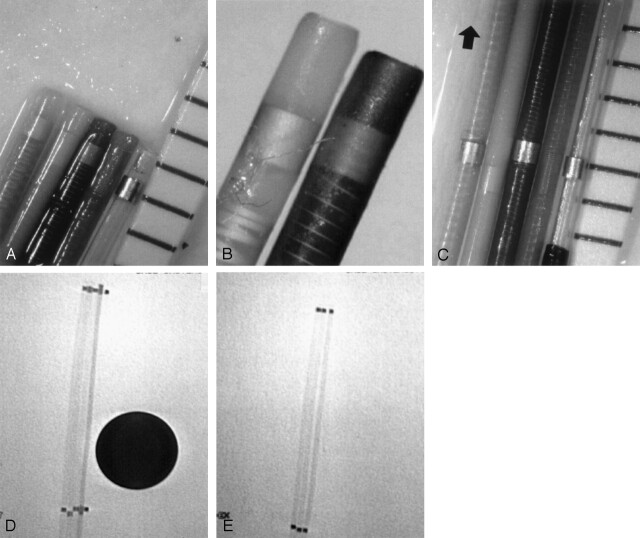
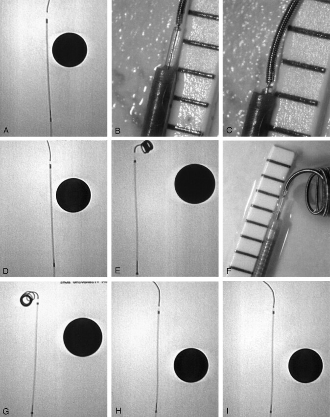
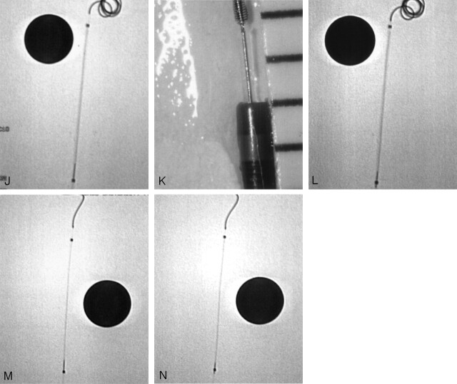
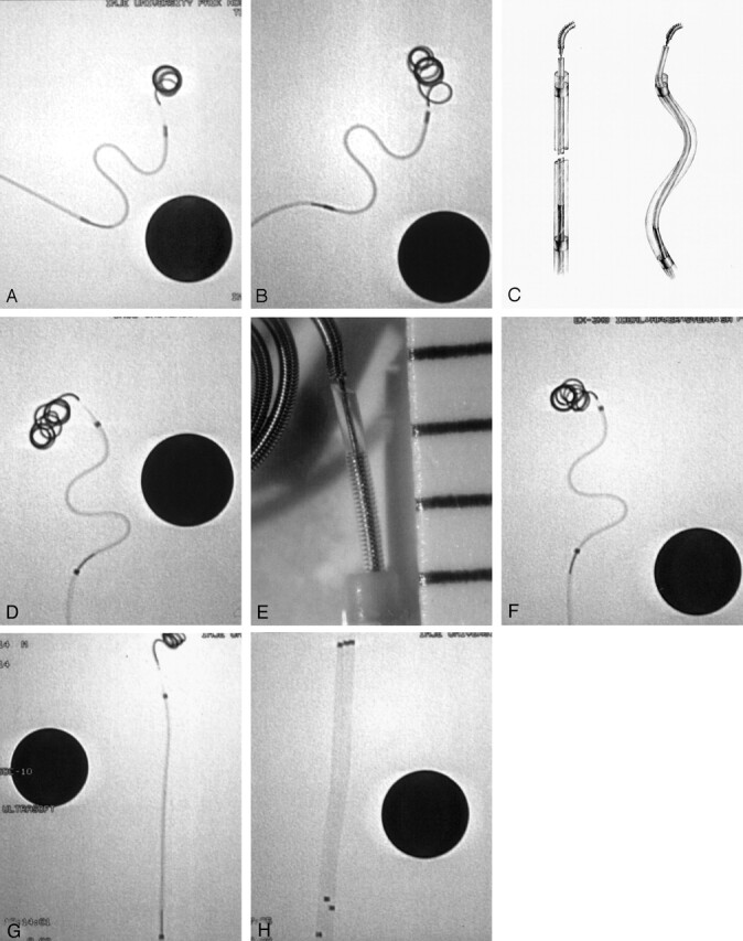
Methods: Six types of commonly used microcatheters were tested (Excel-14, Excelsior, FasTracker-10, Prowler-10, Prowler-14, and Rebar-14). First, the catheter markers and the distance from the catheter tip to the distal end of the proximal and distal markers of each catheter were compared. Second, the coil maker was aligned with the catheter marker. Third, the distal 3 cm of the microcatheter was modified by random shaping, with or without steaming. Last, marker alignment was tested with resterilized microcatheters (ethylene oxide gas sterilization).

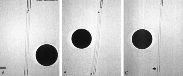
Results: The length of the catheter marker and the distance between the catheter tip and the distal end of the proximal and distal catheter markers varied among the microcatheters. Sometimes, they varied even within the same microcatheter type. When a GDC was advanced until the proximal end of the marker on the delivery wire was exactly distal to the proximal catheter marker, the coil detachment zone was positioned at approximately 1.0 to 1.5 mm outside the catheter tip. Steaming or shaping of the distal 3 cm of the microcatheters resulted in the GDCs protruding more from the catheter tip. Resterilization also had an effect of marker distance shortening. Microcatheters were easily stretched by usual handling, such as removing a shaping mandrel from the catheter tip.

Conclusion: Our study shows that proper marker alignment is influenced by many factors, including microcatheter type, steaming, shaping, sterilization, and manual handling.


Figures

F<sc>ig</sc> 1.
Fig 1.
Fluoroscopic images show distance from proximal end of coil maker to detachment zone of GDC. The diameter of the black circle is 1 cm. A, Distance from proximal end of coil maker to detachment zone of SynerG GDC is approximately 0.2 to 0.3 mm shorter than that of non-SyngerG GDCs. Note the small transparent zone near the real detachment zone (arrow) of the SynerG GDC. B, Fluoroscopic image shows same distance from proximal end of coil maker to detachment zone in both SynerG and non-SynerG GDCs. The microcatheter is an Excelsior. Note the marker alignment and the position of the coil detachment zone from the catheter tip. C, GDC has shorter marker (arrow). Despite the shorter length, the distance from the proximal end of the coil maker to the detachment zone is similar to that of another GDC.
F<sc>ig</sc> 2.
Fig 2.
Photographs and fluoroscopic images show proximal and distal catheter markers, catheter part extended from distal catheter marker (real end of microcatheter), and distance between catheter markers. The diameter of the black circle in the fluoroscopic image is 1 cm. A division of the ruler shown in the photographs (A and C) is 1 mm. A, Photograph shows proximal catheter markers. From left: Excel-14, Rebar-14, Excelsior, Prowler-14, and FasTracker-10. B, Photograph shows that one Excel catheter (left) has longer catheter part beyond distal catheter marker than that of Excelsior (right). It measured 1.68 mm. C, Photograph shows proximal catheter markers. The distal ends of the microcatheters are arranged in the same position as shown in A. Arrow indicates the distal parts of the catheters. D, Fluoroscopic image shows relative locations of proximal catheter markers when distal ends of microcatheters are arranged in similar positions. From left: Excel-14, Rebar-14, Excelsior, Prowler-14, and FasTracker-10. E, Fluoroscopic image shows that one Excelsior has shorter marker distance than another Excelsior. From left: Excelsior, Excelsior, and Excel-14.
F<sc>ig</sc> 3.
Fig 3.
Photographs and fluoroscopic images show position of coil detachment zone with usual marker alignment and marker alignment at ideal alignment. The diameter of the black circle in the fluoroscopic images is 1 cm. A division of the ruler shown in the photographs (B, C, and F) is 1 mm. A, Fluoroscopic image shows usual alignment in Prowler-14. B, Photograph shows position of coil detachment zone in this alignment. C, GDC is retrieved to ideal alignment. D, Proximal end of coil marker is aligned with proximal end of proximal catheter marker. E, Marker alignment and position of coil detachment zone in Excel-14 (fluoroscopic image). F, Marker alignment and position of coil detachment zone in Excel-14 (photograph). G, Ideal alignment in Excel-14. H, Marker alignment and position of coil detachment zone in Rebar-14. I, Ideal alignment in Rebar-14. J, Marker alignment and position of coil detachment zone in Excelsior. K, Marker alignment and position of coil detachment zone in Excelsior. An Excelsior that has a 0.5-mm-shorter marker distance than the other Excelsior catheters (see Fig 2E) is used. L, Ideal alignment in Excelsior. M, Marker alignment and position of coil detachment zone in FasTracker-10. N, Ideal alignment in FasTracker-10.
F<sc>ig</sc> 4.
Fig 4.
Fluoroscopic images and photograph show changes in position of coil detachment zone from catheter tip with catheter manipulations. The diameter of the black circle in the fluoroscopic images is 1 cm. A division of the ruler shown in the photograph (E) is 1 mm. A, Fluoroscopic image shows that random catheter curve (Prowler-10) on distal 3 cm causes coil detachment zone to protrude further from catheter tip. B, Fluoroscopic image shows marker alignment at ideal alignment in same catheter as that shown in A. C, Schematic illustrations show effect of marker distance shortening with catheter curves. The stiff delivery wire maintains a relatively straight course within a tortuous microcatheter (right). The coil is thus more protruded than with a straight catheter (left). Catheter curves without steaming simulate vascular tortuosity. D, Fluoroscopic image shows that steam shaping of an Excel-14 makes coil protrude more from catheter tip than with unmodified Excel-14. E, Photograph shows that steam shaping of Excel-14 makes coil protrude more from catheter tip than with unmodified Excel-14. F, Fluoroscopic image shows marker position at ideal alignment in same catheter. G, Fluoroscopic image shows shortening of marker distance after ethylene oxide gas sterilization. The catheter is an Excel-14. H, Fluoroscopic image shows various lengthening of catheters after gentle manual stretching. All catheters are Excel-14s.

References

    1. Guglielmi G, Viñuela F, Dion J, Duckwiler G. Electrothrombosis of saccular aneurysms via endovascular approach: part 2. preliminary clinical experience. J Neurosurg 1991;75:8–14. - PubMed
    1. Guglielmi G, Viñuela F, Sepetka I, Macellari V. Electrothrombosis of saccular aneurysms via endovascular approach: part 1. electrochemical basis, technique, and experimental results. J Neurosurg 1991;5:1–7 - PubMed

MeSH terms