. 2002 Nov 25;159(4):695-705.
doi: 10.1083/jcb.200204153.

The relationship between force and focal complex development

Affiliations

The relationship between force and focal complex development

Catherine G Galbraith et al. J Cell Biol. .

Abstract

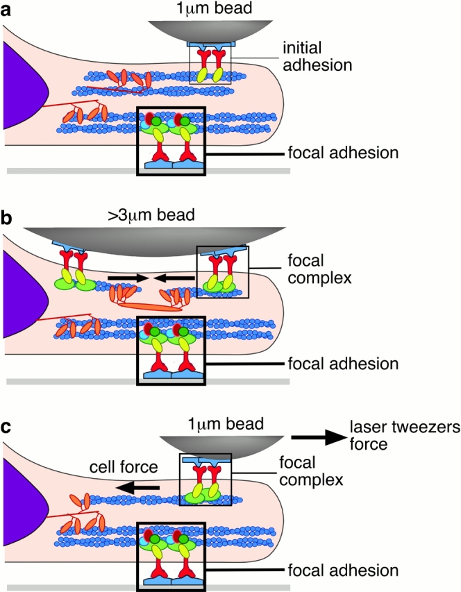
To adhere and migrate, cells must be capable of applying cytoskeletal force to the extracellular matrix (ECM) through integrin receptors. However, it is unclear if connections between integrins and the ECM are immediately capable of transducing cytoskeletal contraction into migration force, or whether engagement of force transmission requires maturation of the adhesion. Here, we show that initial integrin-ECM adhesions become capable of exerting migration force with the recruitment of vinculin, a marker for focal complexes, which are precursors of focal adhesions. We are able to induce the development of focal complexes by the application of mechanical force to fibronectin receptors from inside or outside the cell, and we are able to extend focal complex formation to vitronectin receptors by the removal of c-Src. These results indicate that cells use mechanical force as a signal to strengthen initial integrin-ECM adhesions into focal complexes and regulate the amount of migration force applied to individual adhesions at localized regions of the advancing lamella.


Figures

Figure 1.
Figure 1.
FN7–10-coated beads induce the formation of focal complexes that are inhibited by expression of dominant-negative Rac. (a) The pattern of vinculin accumulation around large, 10-μm-diam FN7–10-coated beads indicates the formation of small punctate focal complexes, whereas vinculin accumulation around full-length FN-coated beads indicates the formation of large focal adhesions. Note that focal planes of the images were chosen to make the vinculin-containing adhesions most visible. Arrows mark adhesions. (b) Focal complexes also form around midsized (6-μm) FN7–10-coated beads, whereas focal adhesions form around the same size full-length FN-coated beads. Insets are higher magnification views of regions around the bead. Bars, 2 μm. (c) The focal complexes formed around 6-μm FN7–10-coated beads are inhibited by expression of dominant-negative Rac (P < 0.005). Expression of dominant- negative Rho or a vector control containing the same promoter did not affect the percentage of beads exhibiting vinculin accumulation. Numbers indicate number of beads scored.
Figure 2.
Figure 2.
Ligand surface area determines the ability to form focal complexes. (a) Vinculin accumulates as punctate focal complexes around 6-μm FN7–10-coated beads (inset, arrows), but it does not accumulate around VN- or Con A–coated beads. Top panels show immunofluorescence labeling of vinculin and bottom panels show DIC images. A circle on the fluorescence image indicates the position of the bead. Insets are higher magnification views of regions around the bead. Bars, 5 μm. (b) Focal complexes do not form around 1-μm FN7–10-coated beads. Insets are higher magnification views of regions around the beads. Bars, 2 μm. (c) Only 6-μm FN7–10-coated beads (FN) induce focal complexes (P < 0.001). VN- and Con A–coated beads do not induce focal complexes. Numbers indicate number of beads.
Figure 3.
Figure 3.
Focal complex formation is dependent upon force. (a) DIC and fluorescent images of ligand-occupied β1 integrin and vinculin when a 6-μm FN7–10-coated bead adheres to a fibroblast lamella. Ligand-occupied β1 integrin and vinculin colocalize (arrows) in the focal complexes induced by the bead. A circle on the fluorescent images indicates the position of the bead. Insets are higher magnification views of regions around the bead. (b) DIC and fluorescent images of ligand-occupied β1 integrin and vinculin when a 6-μm FN7–10-coated bead adheres to a fibroblast lamella in the presence of the myosin light chain kinase inhibitor, ML-7. Vinculin no longer colocalizes with most of the ligand-occupied β1 integrin around the bead (arrows). A circle on the fluorescent images indicates the position of the bead. Insets are higher magnification views of regions around the bead. Bars, 5 μm. (c) Vinculin colocalization with ligand-occupied β1 was significantly inhibited by the absence of force. Force was inhibited by the addition of 15 μM ML-7 (P < 0.0005) to 6-μm FN7–10-coated beads.
Figure 4.
Figure 4.
Focal complexes are formed around small fibronectin-coated beads when external force is applied to the bead by an optical laser trap. (a–c) DIC and fluorescence images of a 1-μm FN7–10-coated bead initially constrained by an optical trap on the surface of a 3T3 fibroblast transfected with GFP-vinculin, illustrating the range of accumulation patterns of GFP-vinculin seen within 30 s around the surface of the bead as it escapes the force of the laser trap. (a) A focal complex formed and curved around a portion of the bead (arrow). (b) A group of focal complexes assembled at the bead perimeter (arrows). (c) A diffuse accumulation containing one or more punctate focal complexes surrounded the bead (arrow). A circle on the fluorescence images indicates the position of the bead. Insets are higher magnification views. Bars, 2 μm. (d) 3T3 fibroblasts were transfected with GFP-vinculin, incubated with 6-μm-diam FN7–10-coated beads, and labeled with anti–vinculin antibody. GFP-vinculin and vinculin antibody show the same localization pattern around beads (arrows). Insets are higher magnification views of the area surrounding the bead. (e) 3T3 fibroblasts were transfected with a GFP control plasmid that contained the same promoter but lacked the vinculin insert. Cells were then incubated with 6-μm-diam FN7–10-coated beads and labeled with anti–vinculin antibody. There was no specific GFP localization around the bead in the negative control (arrow). Insets are higher magnification views of the area surrounding the bead. Bars, 5 μm. (f) GFP localization was specific only in cells transfected with GFP-vinculin (P < 0.001). Numbers indicate number of beads.
Figure 5.
Figure 5.
Vinculin recruitment and focal complex formation follows a typical temporal and spatial pattern. (a–c) Time series of GFP-vinculin accumulation around a 1-μm FN7–10 coated bead initially constrained by an optical trap (t = 0 s). (a) Large arrowheads on DIC images mark the trap position. (b) Fluorescent images show that GFP-vinculin accumulation began as diffuse aggregates that approached the bead from the side of the cell opposite the leading edge (arrow, t = 48 s). GFP-vinculin condensed around the bead (arrow, t = 88, 128 s). GFP-vinculin remained localized at the bead, but it often loses its punctate localization and surrounds the bead (arrow, t = 208 s) as the bead travels inward on the lamella. (c) Pseudocolor images quantify the changes in fluorescence between adjacent images presented in b. Circles on the fluorescence and pseudocolor images indicate the position of the bead. Insets are higher magnification views. Bars, 2 μm.
Figure 6.
Figure 6.
Loss of vinculin binding to a focal complex is accompanied by a decrease in the strength of the cytoskeletal connection. (a) Fluorescence and DIC images of a 1-μm ligand-coated bead constrained by an optical trap on a fibroblast transfected with GFP-vinculin. There is a small amount of GFP-vinculin as the bead begins to escape the trap (arrow, 27 s); there is a much larger recruitment around the bead when it is further from the trap center (arrow, 54 s), but the specific recruitment disappears as the bead returns to the trap center (81 s). Large arrowheads on DIC images mark the trap position. A circle on the fluorescence images indicates the position of the bead. Insets show higher magnification views of the bead. Arrows in the fluorescence insets indicate accumulation. Bars, 1 μm. (b) Immunofluorescence image is the inset from a at 0 s rotated 90° to the left. The circle indicates the bead position, and the horizontal line indicates the line used to measure fluorescence intensity. The fluorescence intensity is plotted as measured from left to right along the immunofluorescence image. The line labeled bead in the graph indicates the bead position. (c) Fluorescent line intensities of high magnification inserts as a function of position. There is a small increase of fluorescence, indicating a small increase in the amount of vinculin, on the side of the bead toward the leading edge of the cell at 27 s. At 54 s, there is an increase of fluorescence on both sides of the bead. At 81 s, the fluorescent intensity is similar to that at 27 s, but there is still a slight elevation underneath the bead.
Figure 7.
Figure 7.
Sustained vinculin recruitment indicates strengthened connections between fibronectin receptor and the cytoskeleton. (a) FN–integrin–cytoskeletal connection is reinforced. FN7–10-coated bead escapes from the optical trap; the trap is turned off, and the stage is repositioned. The trap is turned on again, and the bead does not return to the center of the trap. Note that the origin of the displacement trace has been repositioned during the stage repositioning so that all displacements appear to be positive. Arrowheads mark trap position. (b) VN–integrin–cytoskeletal connection is not reinforced. The VN-coated bead jumps to the center of the trap when trap is turned on again. Arrowheads mark trap position. Bar, 1 μm. (c) Con A–integrin–cytoskeletal connection is also not reinforced. (d) Only connections made between FN7–10-coated beads, fibronectin receptors, and cytoskeleton showed significant vinculin recruitment (P < 0.05) and reinforcement (P < 0.005). Numbers indicate number of beads.
Figure 8.
Figure 8.
c-Src regulates whether focal complexes form with VN receptors. (a) Vinculin accumulates around 6-μm VN-coated beads on c-Src −/− cells (inset, arrows), but not around +/+ or −/− wild-type cells. A circle on the fluorescence images indicates the position of the bead. Insets show higher magnification views of the bead. Arrows in the fluorescence insets indicate accumulation. Bars, 5 μm. (b) Percentage of FN7–10, VN, and Con A–coated 6-μm beads displaying vinculin recruitment on c-Src cells. Vinculin recruitment is sensitive to c-Src expression only with the VN-coated beads (P < 0.05). Numbers indicate number of beads.
Figure 9.
Figure 9.
Focal complexes formed with VN receptors recruit vinculin as they exert migration force. (a) DIC and fluorescence images of a 1-μm VN-coated bead constrained by an optical trap on a c-Src −/− cell transfected with GFP-vinculin. The bead is in contact with the cell at 0+ s. Vinculin was recruited to the side of the bead as it escaped the trap (arrow, 54 s). More vinculin is recruited to the periphery of the bead with time (72 s). A circle on the fluorescence images indicates the position of the bead. Arrows mark trap position in DIC images. Insets show higher magnification views of the area surrounding the bead. Bars, 1 μm. (b) Percentage of FN7–10 or VN-coated beads showing reinforcement on c-Src −/− and c-Src +/+ cells. VN linkages only reinforce on c-Src −/− cells (P < 0.05). Numbers indicate number of beads.
Figure 10.
Figure 10.
Mechanical force determines the type of adhesive complexes formed as ligand-coated surfaces bind to integrin receptors. (a) The initial adhesions between a small ligand-coated surface and integrin receptors produce an initial adhesion that moves rearward with retrograde actin flow. A focal adhesion can be formed against a larger ligand-coated surface that is physically restrained. More intracellular proteins are involved in the focal adhesion than the focal complex. (b) Midsized ligand-coated surfaces allow the cytoskeleton to contract mechanically, and they signal for the recruitment of proteins involved in focal complex formation. (c) Focal complexes can also be formed if mechanical force is applied externally by a laser trap.

References

    1. Balaban, N.Q., U.S. Schwarz, D. Riveline, P. Goichberg, G. Tzur, I. Sabanay, D. Mahalu, S. Safran, A. Bershadsky, L. Addadi, and B. Geiger. 2001. Force and focal adhesion assembly: a close relationship studied using elastic micropatterned substrates. Nat. Cell Biol. 3:466–472. - PubMed
    1. Beningo, K.A., M. Dembo, I. Kaverina, J.V. Small, and Y.L. Wang. 2001. Nascent focal adhesions are responsible for the generation of strong propulsive forces in migrating fibroblasts. J. Cell Biol. 153:881–888. - PMC - PubMed
    1. Bloom, L., K.C. Ingham, and R.O. Hynes. 1999. Fibronectin regulates assembly of actin filaments and focal contacts in cultured cells via the heparin-binding site in repeat III13. Mol. Biol. Cell. 10:1521–1536. - PMC - PubMed
    1. Chen, C.S., M. Mrksich, S. Huang, G.M. Whitesides, and D.E. Ingber. 1997. Geometric control of cell life and death. Science. 276:1425–1428. - PubMed
    1. Choquet, D., D.P. Felsenfeld, and M.P. Sheetz. 1997. Extracellular matrix rigidity causes strengthening of integrin-cytoskeleton linkages. Cell. 88:39–48. - PubMed

Publication types

MeSH terms