

Review
doi: 10.1136/bmj.326.7399.1137.
ABC of interventional cardiology: percutaneous coronary intervention. II: the procedure
Affiliations
- PMID: 12763994
- PMCID: PMC514052
- DOI: 10.1136/bmj.326.7399.1137
Item in Clipboard
Review
ABC of interventional cardiology: percutaneous coronary intervention. II: the procedure
BMJ.
.
No abstract available
Figures
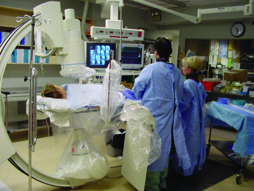
Percutaneous coronary intervention in progress. Above the patient's
chest is the x ray imaging camera. Fluoroscopic images, electrocardiogram, and
haemodynamic data are viewed at eye level screens. All catheterisation
laboratory operators wear lead protection covering body, thyroid, and eyes,
and there is lead shielding between the primary operator and patient
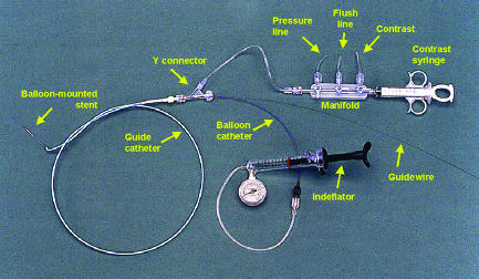
Equipment commonly used in percutaneous coronary interventions
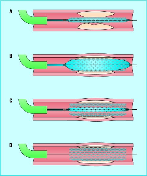
Deployment of a balloon-mounted stent across stenotic lesion. Once the
guide catheter is satisfactorily engaged, the lesion is crossed with a
guidewire and the balloon-mounted stent positioned to cover the lesion (A). It
may be necessary to pre-dilate a severe lesion with a balloon to provide
adequate passageway for the balloon and stent. The balloon is inflated to
expand the stent (B). The balloon is then deflated (C) and withdrawn leaving
the guidewire (D), which is also removed once the operator is satisfied that a
good result has been obtained
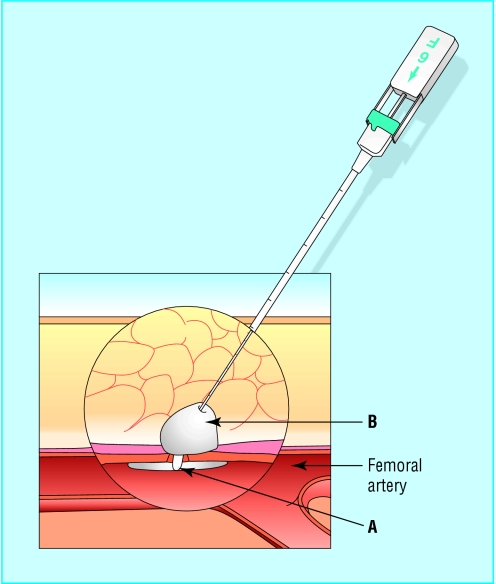
Example of a femoral artery closure device. The Angio-Seal device
creates a mechanical seal by sandwiching the arteriotomy between an anchor
placed against the inner arterial wall (A) and collagen sponge (B), which both
dissolve within 60-90 days
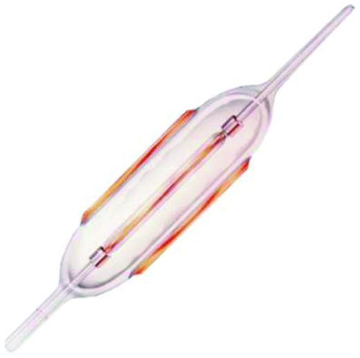
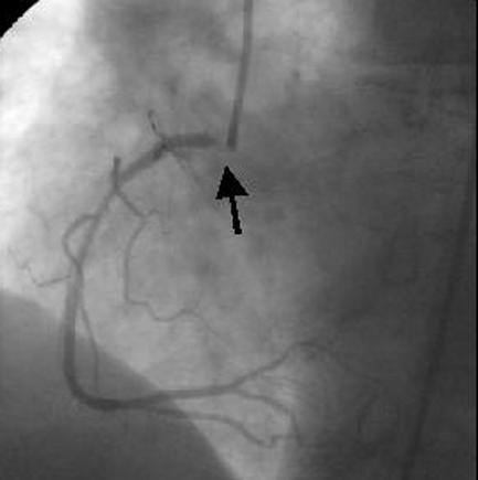
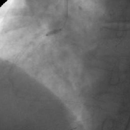
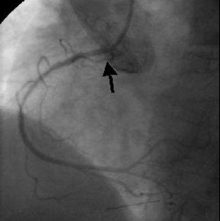
The cutting balloon catheter. The longitudinal cutting blades are
exposed only during balloon inflation (top left). In this case (top right) a
severe ostial in-stent restenosis in the right coronary artery (arrow) was
dilated with a short cutting balloon (bottom left), and a good angiographic
result was obtained (arrow, bottom right)
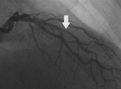
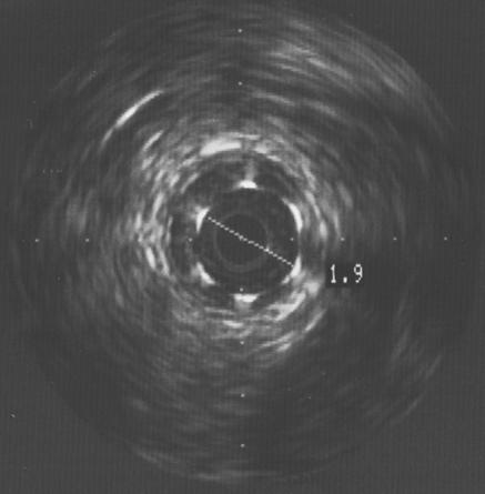
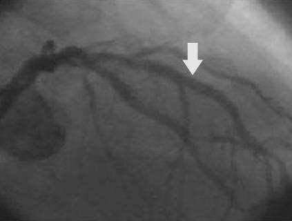
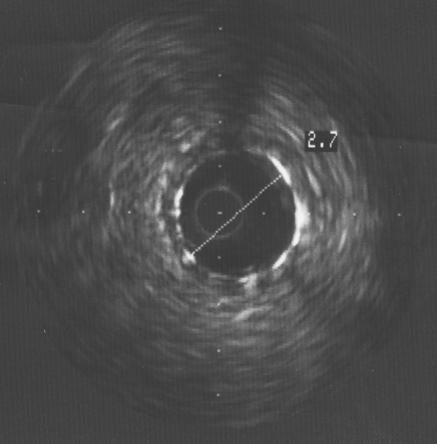
Focal in-stent restenosis. A 2.0 mm stent had been deployed six months
earlier. After recurrence of angina, angiography showed focal in-stent
restenosis (arrow, top left). This was confirmed with intravascular ultrasound
(top right), which also revealed that the stent was underexpanded. The stent
was further expanded with a balloon catheter, with a good angiographic result
(arrow, bottom left) and an increased lumen diameter to 2.7 mm (bottom
right)
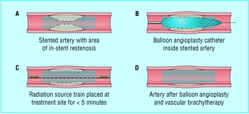
Diagrammatic representation of the Novoste Beta Cath system used for
vascular brachytherapy. Pre-dilatation of the in-stent restenosis with a
balloon catheter is usual and is followed by positioning of the radiation
source train, containing strontium-90, at the site for less than 5
minutes
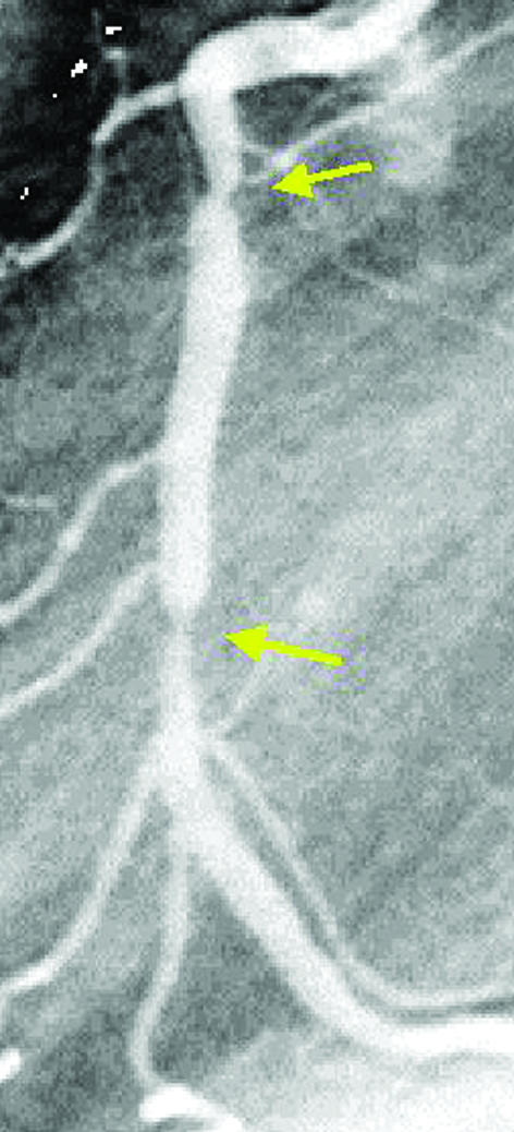
Angiogram showing late “candy wrapper” edge effect (arrows)
because of new restenosis at the edges of a segment treated by
brachytherapy
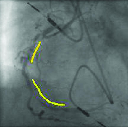
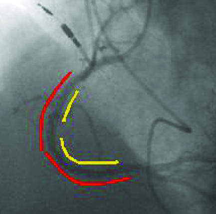
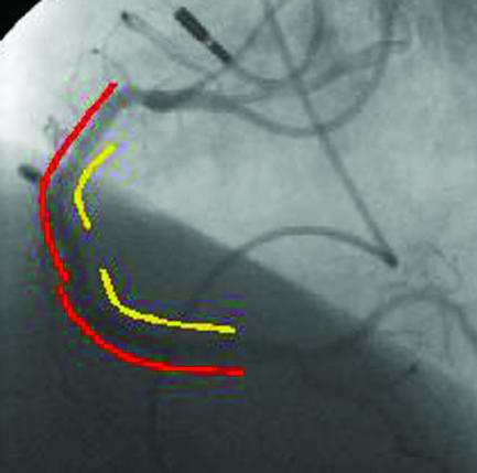
Top left: four months after two stents (yellow lines) were deployed in
the proximal and middle right coronary artery, severe diffuse in-stent
restenosis has occurred with recurrent angina. Top right: two sirolimus coated
Cypher stents (red lines) were deployed within the original stents. Bottom:
after six months there was no recurrence of restenosis, and the 51 year old
patient remained asymptomatic
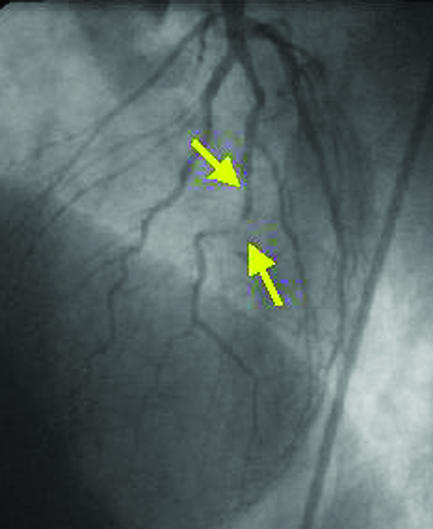
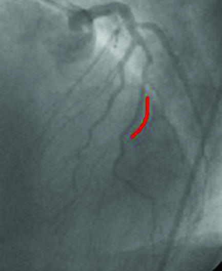
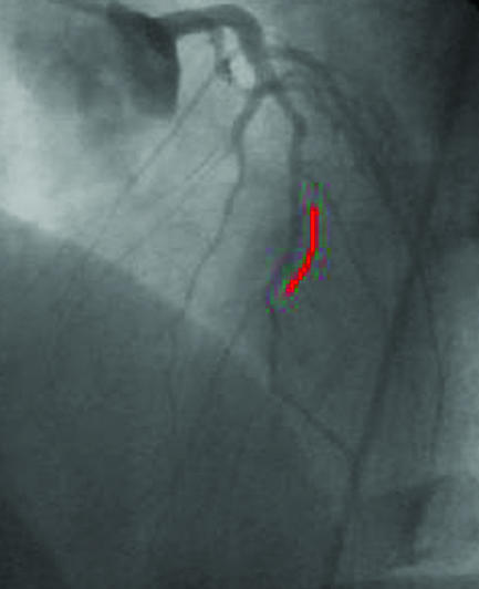
The incidence of restenosis is particularly high with percutaneous
revascularisation of small vessels. A small diseased diagonal artery (arrows,
top left) in a 58 year old patient with limiting angina was stented with a
sirolimus coated Cypher stent (red line, top right). After six months, no
restenosis was present (left), and the patient remained asymptomatic
Similar articles
-
We can build it, but will they come?Catheter Cardiovasc Interv. 2011 May 1;77(6):818-9. doi: 10.1002/ccd.23131. Catheter Cardiovasc Interv. 2011. PMID: 21520383 No abstract available.
-
If I've heard it once, I've heard it (not yet) a hundred times.Catheter Cardiovasc Interv. 2011 Mar 1;77(4):502. doi: 10.1002/ccd.22989. Catheter Cardiovasc Interv. 2011. PMID: 21351224 No abstract available.
-
Optimizing the impact of primary percutaneous coronary intervention in acute myocardial infarction.Catheter Cardiovasc Interv. 2011 Feb 1;77(2):201. doi: 10.1002/ccd.22952. Catheter Cardiovasc Interv. 2011. PMID: 21290554 No abstract available.
-
[Percutaneous coronary interventions for acute coronary syndrome and left coronary arterial trunk lesion: state-of-the-art].Vestn Rentgenol Radiol. 2011 Jul-Aug;(3):64-8. Vestn Rentgenol Radiol. 2011. PMID: 22288138 Review. Russian. No abstract available.
-
ABC of interventional cardiology: percutaneous coronary intervention. I: history and development.BMJ. 2003 May 17;326(7398):1080-2. doi: 10.1136/bmj.326.7398.1080. BMJ. 2003. PMID: 12750213 Free PMC article. Review. No abstract available.
Cited by
-
Impact of renin angiotensin system inhibitor on 3-year clinical outcomes in acute myocardial infarction patients with preserved left ventricular systolic function: a prospective cohort study from Korea Acute Myocardial Infarction Registry (KAMIR).BMC Cardiovasc Disord. 2021 May 21;21(1):251. doi: 10.1186/s12872-021-02070-x. BMC Cardiovasc Disord. 2021. PMID: 34020593 Free PMC article.
-
Antegrade balloon occlusion of inferior vena cava during thrombectomy for renal cell carcinoma.Can Urol Assoc J. 2010 Aug;4(4):E105-8. doi: 10.5489/cuaj.892. Can Urol Assoc J. 2010. PMID: 20694087 Free PMC article.
-
ST-elevation versus non-ST-elevation myocardial infarction after combined use of statin with renin-angiotensin system inhibitor: Data from the Korea Acute Myocardial Infarction Registry.Cardiol J. 2022;29(4):647-659. doi: 10.5603/CJ.a2021.0007. Epub 2021 Feb 26. Cardiol J. 2022. PMID: 33634844 Free PMC article.
-
Incremental predictive value of the combined use of the neutrophil-to-lymphocyte ratio and systolic blood pressure difference after successful drug-eluting stent implantation.Cardiol J. 2023;30(1):91-104. doi: 10.5603/CJ.a2021.0004. Epub 2021 Jan 13. Cardiol J. 2023. PMID: 33438177 Free PMC article.
-
Xiongshao for restenosis after percutaneous coronary intervention in patients with coronary heart disease.Cochrane Database Syst Rev. 2013 May 31;2013(5):CD009581. doi: 10.1002/14651858.CD009581.pub2. Cochrane Database Syst Rev. 2013. PMID: 23728695 Free PMC article.
References
-
- Smith SC Jr, Dove JT, Jacobs AK, Kennedy JW, Kereiakes D, Kern MJ, et al. ACC/AHA guidelines of percutaneous coronary interventions (revision of the 1993 PTCA guidelines)—executive summary. A report of the American College of Cardiology/American Heart Association Task Force on Practice Guidelines (committee to revise the 1993 guidelines for percutaneous transluminal coronary angioplasty). J Am Coll Cardiol 2001;37: 2215-39 - PubMed
-
- Morice MC, Serruys PW, Sousa JE, Fajadet J, Ban Hayashi E, Perin M, et al. A randomized comparison of a sirolimus-eluting stent with a standard stent for coronary revascularization. N Engl J Med 2002;346: 1773-80 - PubMed
-
- Almond DG. Coronary stenting I: intracoronary stents—form, function future. In: Grech ED, Ramsdale DR, eds. Practical interventional cardiology. 2nd ed. London: Martin Dunitz, 2002: 63-76
-
- Waksman R. Management of restenosis through radiation therapy. In: Grech ED, Ramsdale DR, eds. Practical interventional cardiology. 2nd ed. London: Martin Dunitz, 2002: 295-305
-
- Kimmel SE, Berlin JA, Laskey WK. The relationship between coronary angioplasty procedure volume and major complications. JAMA 1995;274: 1137-42 - PubMed
Publication types
MeSH terms
LinkOut - more resources
Full Text Sources
Other Literature Sources