. 2003 Jun;84(6):3968-81.
doi: 10.1016/S0006-3495(03)75124-8.

Nonresonant confocal Raman imaging of DNA and protein distribution in apoptotic cells

Affiliations

Nonresonant confocal Raman imaging of DNA and protein distribution in apoptotic cells

N Uzunbajakava et al. Biophys J. 2003 Jun.

Abstract

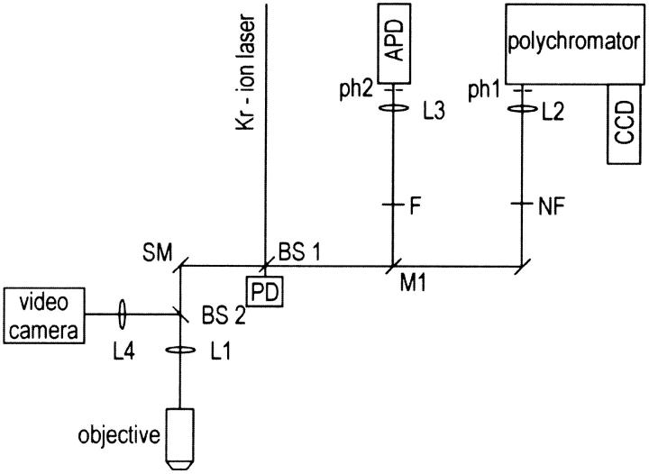
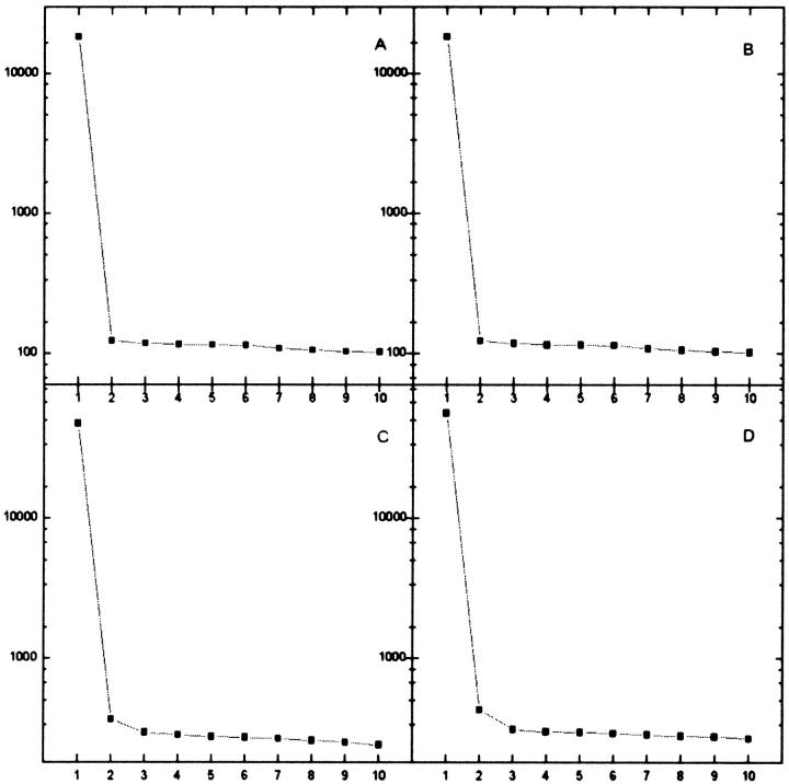
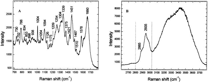
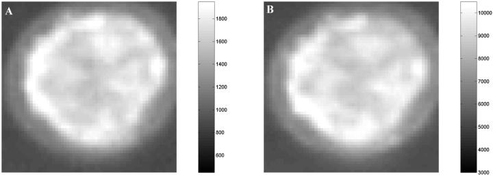
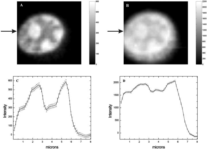
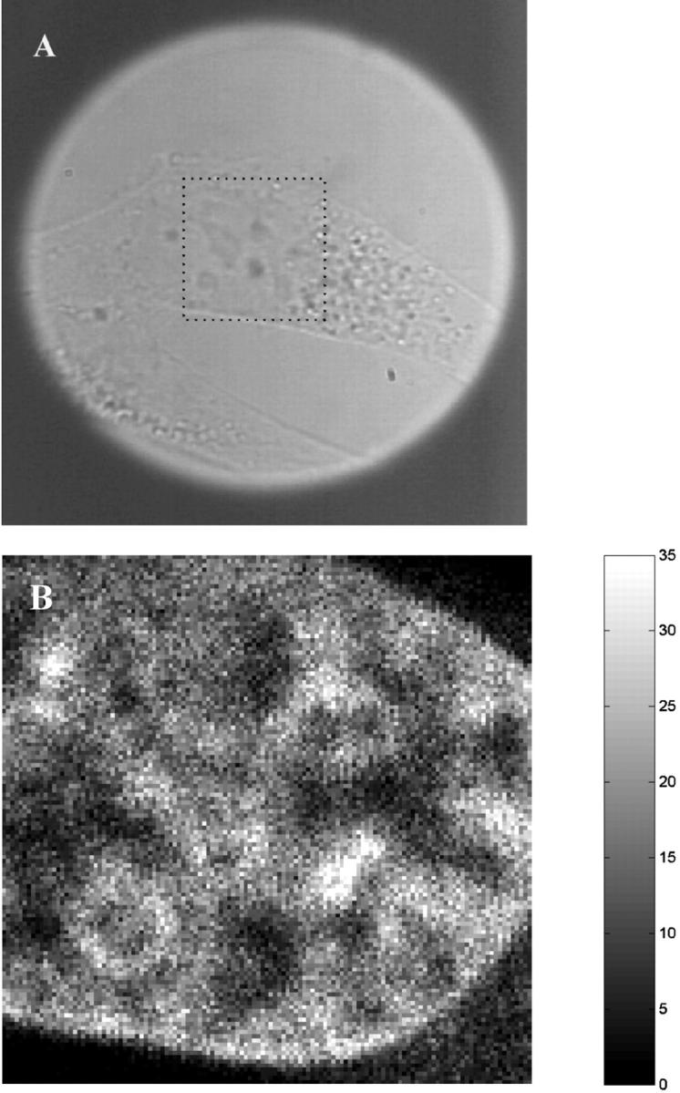
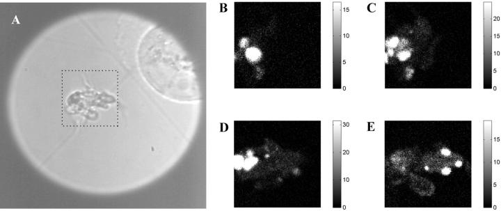
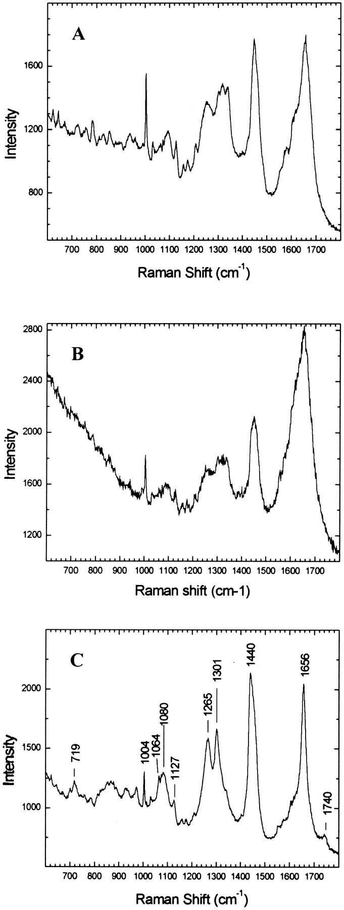
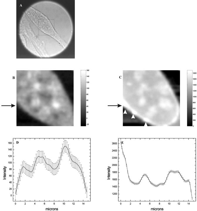
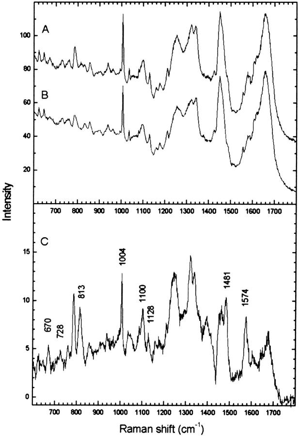
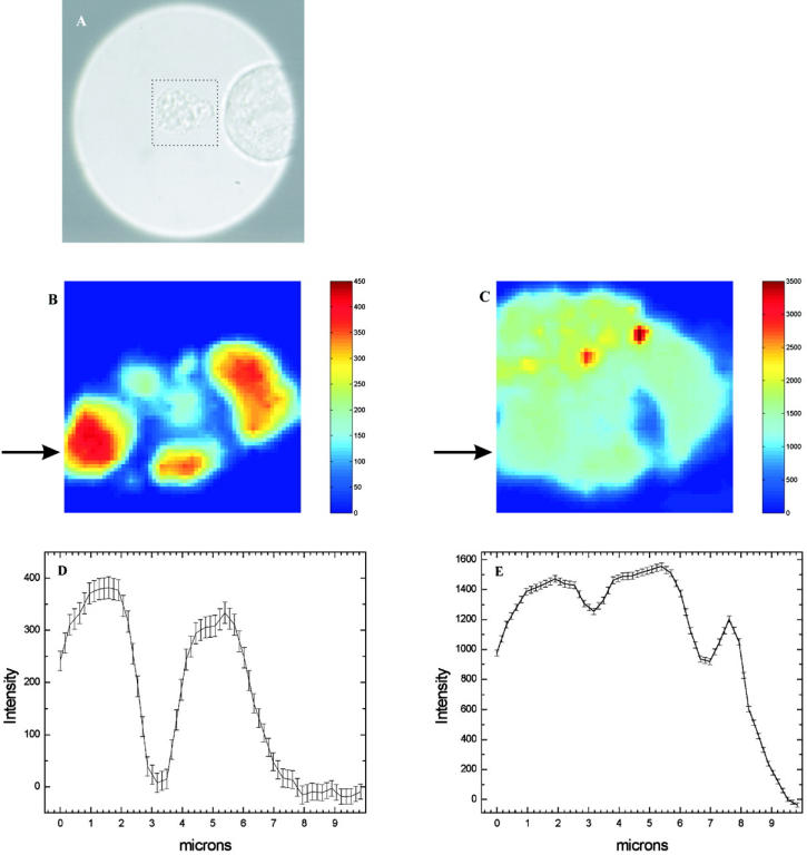
Nonresonant confocal Raman imaging has been used to map the DNA and the protein distributions in individual single human cells. The images are obtained on an improved homebuilt confocal Raman microscope. After statistical analysis, using singular value decomposition, the Raman images are reconstructed from the spectra covering the fingerprint region. The data are obtained at a step interval of approximately 250 nm and cover a field from 8- to 15- micro m square in size. Dwell times at each pixel are between 0.5 and 2 s, depending on the nature and the state of the cell under investigation. High quality nonresonant Raman images can only be obtained under these conditions using continuous wave high laser powers between 60 and 120 mW. We will present evidence that these laser powers can still safely be used to recover the chemical distributions in fixed cells. The developed Raman imaging method is used to image directly, i.e., without prior labeling, the nucleotide condensation and the protein distribution in the so-called nuclear fragments of apoptotic HeLa cells. In the control (nonapoptotic) HeLa cells, we show, for the first time by Raman microspectroscopy, the presence of the RNA in a cell nucleus.


Figures

FIGURE 1
FIGURE 1
Confocal Raman/TPE fluorescent microscope. Both Raman and fluorescent signals were excited with 647.1 nm line of a Kr-ion laser (Innova 90-K, Coherent). The excitation and the detection wavelengths were separated by use of a dichroic beamsplitter (BS1) (Chroma Technology). Images were acquired by scanning the sample with a scanning mirror (SM) (Leica Lasertechnique GmbH, Heidelberg, Germany). The laser beam, focused by a water immersion objective (Zeiss Plan Neofluar, Carl Zeiss), formed a diffraction-limited spot on the sample. A mobile pellicle beamsplitter (BS2) (Melles Griot) was used to visualize the object in white light. White light was focused by a lens (L4) (f = 100 mm) on a video camera. A holographic notch filter (NF) (Kaiser Optical Systems, Ann Arbor, MI) was used to suppress both reflected and elastically scattered light. A polychromator (Jobin-Yvon, Paris, France) with a blazed holographic grating (600 gr/mm) was used for dispersion. The Raman scattered light was focused on the confocal pinhole (ph1) (diameter, 25 μm) at the entrance of the monochromator by a lens (L2) (f = 35 mm). Raman signal was detected by a CCD camera (LN/CCD 1100 PB/VISAR, Roper Scientific). The output power of the laser source was monitored by a photodiode (PD). A movable mirror (M1) (Newport) was used to switch between Raman and fluorescent signal acquisition modes. A colored glass filter (F) (Melles Griot) was used to suppress the laser light and to transmit the two-photon excited fluorescence signal. Fluorescent signal was focused on a confocal pinhole (ph2) (diameter, 25 μm) by a lens (L3) (f = 30 mm) and was detected on an APD (EG&G, Canada, Ltd., Optoelectronics Division).
FIGURE 2
FIGURE 2
Semilogarithmic plots of the singular values of 10 consecutive spectra obtained at a single location in the cell nucleus. The measurement time for each spectrum was 10 s. Results are shown for four different powers: (A) 10 mW; (B) 30 mW; (C) 70; and (D) 100 mW. It is observed that the spectra are dominated by a single spectral component. Starting from 70 mW, a very small additional component can be observed that is further increased at higher laser powers.
FIGURE 3
FIGURE 3
Raman spectra of the nuclei of single fixed PBLs. (A) The fingerprint region of the spectrum. (B) The high frequency region of the spectrum. The cells were adhered to CaF2 disk, which was immersed in PBS buffer. The laser power was 30 mW, and the accumulation time was 60 s.
FIGURE 4
FIGURE 4
Raman images of the protein distribution in a single fixed PBL cell. (A) Image made in the 1449 cm−1 (spectral region from 1433 cm−1 to 1481 cm−1) band. (B) In the high frequency band ∼2880 cm−1 (spectral region from 2800 cm−1 to 3030 cm−1). Raman images A and B were acquired simultaneously. The pixels on the CCD camera along the spectral dimension were hardware-binned in groups having a size of 5 pixels. The spectral resolution of the superpixel was 8.5 cm−1. The camera offset was subtracted. The scanning area was 8 μm × 8 μm. Laser power was 120 mW, and the acquisition time was 1 s per step.
FIGURE 5
FIGURE 5
Raman images of a single fixed PBL cell on a CaF2 substrate, immersed in PBS buffer. (A) The DNA/RNA image, reconstructed in the 788 cm−1 band (spectral region from 774 cm−1 to 805 cm−1). (B) The protein image, reconstructed in 1451 cm−1 band (spectral region from 1431 cm−1 to 1481 cm−1). (C and D) The line profiles with the SDs through the DNA- and protein image, respectively. The SD intervals are shown as 2σ interval and were calculated using Eq. 2. The background intensity due to water and the camera offset was subtracted. The scanning area was 8.4 μm × 8.4 μm. The laser power was 100 mW, and the acquisition time was 2 s per step.
FIGURE 6
FIGURE 6
(A) A white light image of a control HeLa cell. (B) The DNA distribution as obtained by two-photon excitation of the DNA dye, Hoechst 33342. The signal is detected on the APD. The color scale is given in counts, detected on the APD. The scanning area was 15 μm × 15 μm in 128 × 128 steps. The cw-laser power was 100 mW, and the accumulation time was 1 ms/pixel.
FIGURE 7
FIGURE 7
The DNA distribution in an apoptotic HeLa cell. (A) White light image of an apoptotic HeLa cell. (From BE) The DNA distribution as obtained by two-photon excitation of the DNA marker, Hoechst 33342. Optical sections are made at the different z-positions (Δz = 2 μm) inside the cell. The scanning x-y range was 15 μm × 15 μm in 128 × 128 steps. The cw-laser power was 100 mW, and the accumulation time was 1 ms/pixel. Each image was scaled from ‘0’ to the 30% of the maximum intensity.
FIGURE 8
FIGURE 8
The Raman spectra obtained at the different locations inside a single fixed control HeLa cell. (A) The nucleus spectrum, average of seven spectra. (B) The cytosol spectrum, obtained at a single location. (C) The spectrum of the phospholipid-containing vesicles, average of five spectra. The cell was adhered to a CaF2 disk, immersed in PBS buffer. The laser power was 100 mW, and the accumulation time was 60 s.
FIGURE 9
FIGURE 9
Raman imaging of a single fixed control HeLa cell. The cell was adhered to a CaF2 disk, immersed in PBS buffer. (A) The bright light view of the cell. The dotted rectangle indicates the scanning area. (B) The image, reconstructed in 788 cm−1 band (spectral region from 776 cm−1 to 805 cm−1). (C) Image, reconstructed in 1451 cm−1 band (spectral region from 1431 cm−1 to 1473 cm−1). (D) The line profile through image B with the SD. (E) The line profile through image C with the SD. The SD intervals are shown as 2σ interval and were calculated using Eq. 2. The scanning area was 15 μm × 15 μm. The laser power was 100 mW, and the acquisition time was 2 s per step.
FIGURE 10
FIGURE 10
Average and difference Raman spectra obtained in a nucleus of the HeLa cell. (A) Average spectrum obtained from the bright intensity regions, visible in the image made in 788 cm−1 band. (B) Average spectrum obtained from the regions between the bright intensity regions. (C) Difference spectrum of A and B. Spectrum A was obtained by averaging of 41 individual spectra, and spectrum B by averaging of 103 individual spectra.
FIGURE 11
FIGURE 11
Raman imaging of a single fixed apoptotic HeLa cell. The cell was adhered to a CaF2 disk, immersed in PBS buffer. (A) A bright light view of the cell. The dotted rectangle indicates the scanning area. (B) DNA image, reconstructed in 788 cm−1 band (spectral region from 774 cm−1 to 805 cm−1). (C) Protein image, reconstructed in 1451 cm−1 band (spectral region from 1434 cm−1 to 1474 cm−1). (D) Line profile with the SD through the DNA image. (E) Line profile with the SD through the protein image. The SD intervals are shown as 2σ interval, and were calculated using Eq. 2. The background intensity due to the Raman scattering of water and the camera offset was subtracted. The scanning area was 10 μm × 10 μm. The laser power was 100 mW, and the acquisition time was 1 s per step.

Similar articles

Cited by

References

    1. Arikan, S., H. S. Sands, R. G. Rodway, and D. N. Batchelder. 2002. Raman spectroscopy and imaging of beta-carotene in live corpus luteum cells. Anim. Reprod. Sci. 71:249–266. - PubMed
    1. Biggiogera, M., M. G. Bottone, and C. Pellicciari. 1998. Nuclear RNA is extruded from apoptotic cells. J. Histochem. Cytochem. 46:999–1005. - PubMed
    1. Byassee, T. A., W. C. Chan, and S. Nie. 2000. Probing single molecules in single living cells. Anal. Chem. 72:5606–5611. - PubMed
    1. Cheng, J.-X., A. Volkmer, L. D. Book, and X. S. Xie. 2001. An epi-detected anti-Stokes Raman scattering (E-CARS) microscope with high spectral resolution and high sensitivity. J. Phys. Chem. B. 105:1277–1280.
    1. Cheng, J.-X., A. Volkmer, L. D. Book, and X. S. Xie. 2002. Multiplex coherent anti-Stokes Raman scattering microspectroscopy and study of lipid vesicles. J. Phys. Chem. B. 106:8493–8498.

MeSH terms

LinkOut - more resources