

Percutaneous vertebroplasty: complication avoidance and technique optimization
Affiliations
- PMID: 13679295
- PMCID: PMC7973982
Item in Clipboard
Percutaneous vertebroplasty: complication avoidance and technique optimization
AJNR Am J Neuroradiol.
2003 Sep.
No abstract available
Figures
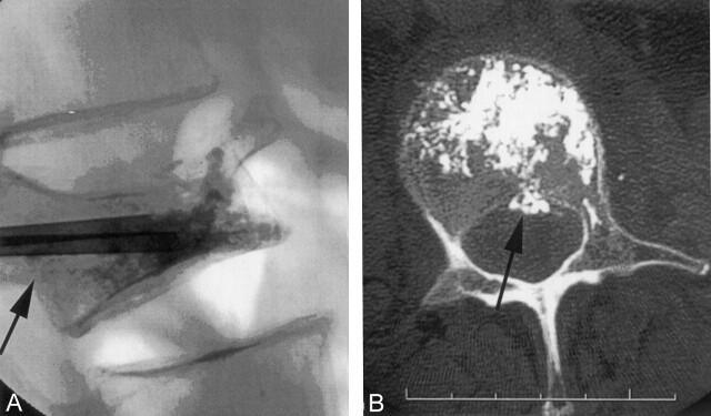
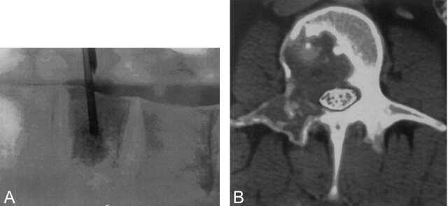
A, Lateral radiograph during vertebroplasty showing cement extending to the posterior vertebral margin (black arrow). B, Post-PV CT scan demonstrates a small leak into the epidural venous plexus (black arrow). This leak was asymptomatic.
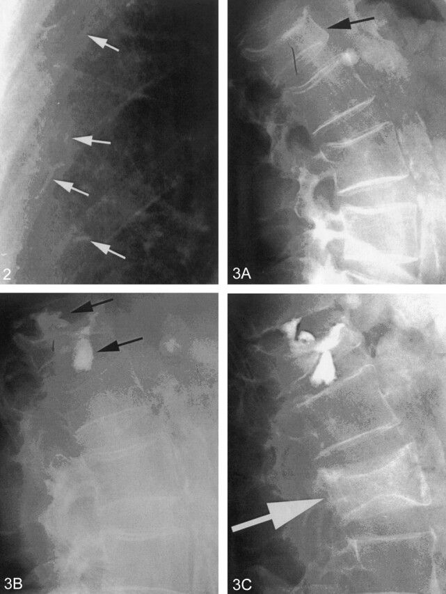
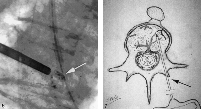
Portion of a chest radiograph after PV showing small radiopaque cement emboli (white arrows) in peripheral pulmonary vessels. This patient had no pulmonary symptoms.
A, Lateral radiograph of the spine showing a moderately compressed vertebra (black arrow). B, Postvertebroplasty, there are large leaks of cement (black arrows) into the adjacent disk spaces. C, Six months later, the patient returned with a second fracture (white arrow). This fracture is not an adjacent level. Adjacent levels did not fracture despite the large disk leaks.
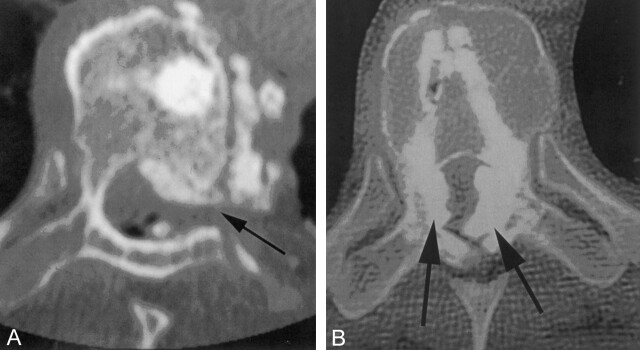
A, Postvertebroplasty CT scan demonstrates large cement leaks into the spinal canal, neural foramin (black arrow), and perispinus region. This patient had paresis and radiculopathy. B, Postkyphoplasty CT scan shows large leaks into the spinal canal (black arrows), which created paraplegia.
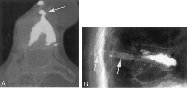
A, Postkyphoplasty CT scan. The lateral wall was disrupted by the balloon inflation, and a large cement leak into the mediastinum resulted (white arrow). For weeks following the procedure, this patient had severe, persistent pain. B, Lateral radiography after vertebroplasty with a slow-set PMMA. The needles were withdrawn and the cement was still liquid enough to flow into the needle tracts and into the soft tissue (white arrows). This created local discomfort to pressure.
Radiograph showing appropriately opacified cement (white arrow) that can be easily seen even in very small quantities.
Drawing depicting the needle entry site into the bone (black arrow) for a transpedicular approach. Following removal of the needle, local pressure allows one to easily achieve hemostasis in this situation.
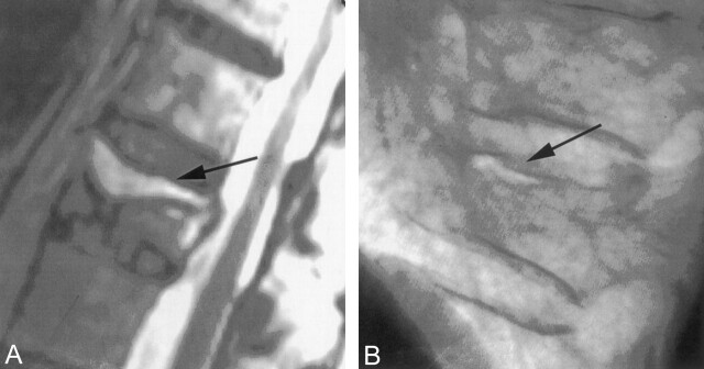
A, T2 sagittal MR imaging demonstrating a high signal intensity collection (black arrow) below the superior endplate of this compressed vertebra. This represents a fluid-filled vertebral cleft. B, Lateral radiograph showing an air-filled cleft (black arrow) in a compression fracture.
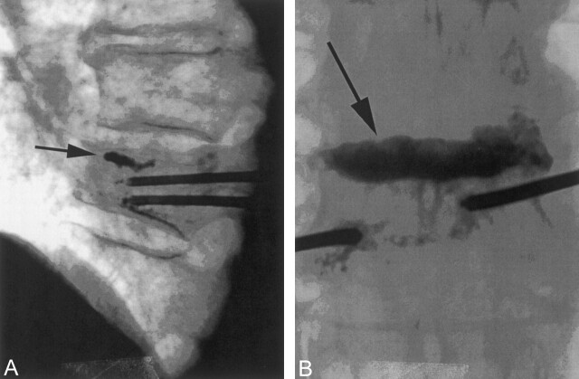
A, Lateral radiograph showing early cement filling of a cleft below the superior endplate (black arrow) of a compressed vertebra. Note that the needle tips are separated from the cleft and the cleft is filling preferentially. B, Anterioposterior view of the same vertebra at completion of the vertebroplasty. The cleft (black arrow) has been completely filled with cement. Relatively little cement has been deposited into the rest of the vertebra. This typically results in good pain relief without the need for repeat filling of the noncleft portion of the vertebra.
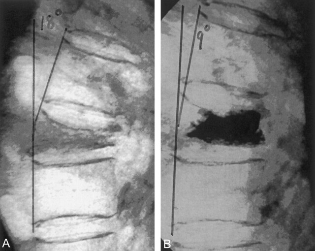
A, Lateral radiograph demonstrating marked compression of a lower thoracic vertebra. Note the 18° of kyphosis before vertebroplasty. B, With mild extension of the body, some height was restored to vertebra during vertebroplasty. This postvertebroplasty image shows that the kyphosis has been reduced to 9°.
A, Lateral radiograph during vertebroplasty of a compression fracture due to breast carcinoma. Note that the thecal sac was first opacified with myelographic contrast. This allows one to watch for deformation of the thecal sac that would indicate tumor displacement during cement introduction. B, With the thecal sac opacified, axial CT scans provide the most sensitive method to monitor PV for thecal sac compression created by tumor displaced during cement injection.
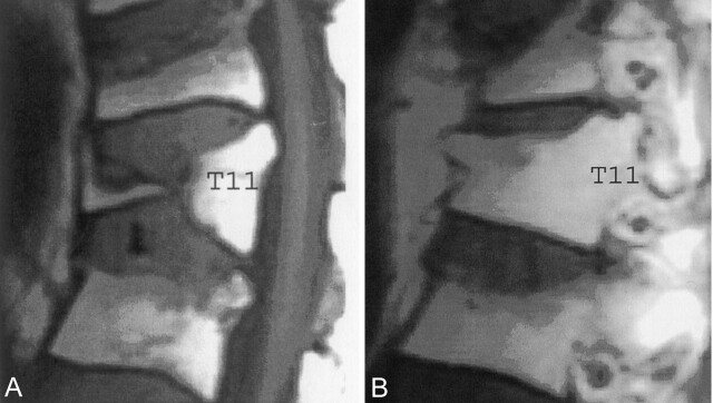
A, Sagittal T1 MR imaging (midline) showing complete central compression of T11. B, Sagittal T1 MR imaging (lateral vertebral margin) reveals considerable residual marrow space that could be filled with cement during vertebroplasty.
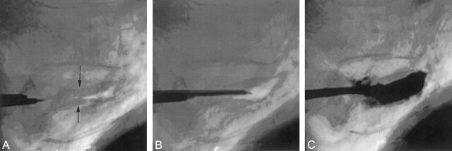
A, Lateral radiograph of an extremely collapsed lower thoracic vertebra. Superior and inferior endplates are identified (black arrows). There is a small air-filled cleft; 13-gauge needles are being introduced via transpedicular route. B, A lateral image showing one 13-gauge needle in good position before vertebroplasty. C, Final image after bipedicular vertebroplasty. Good filling of the vertebra was achieved despite the severe collapse. The patient had a good pain response to the procedure.
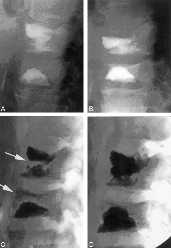
A, Lateral radiograph following a two-level vertebroplasty. B, Follow-up lateral radiograph after refracture of both previously treated levels. Both levels show height loss compared with image shown in panel A. C, With the patient placed in mild extension on the angiographic table, the two vertebrae show height restoration and the development of internal clefts (white arrows). D, The final image following vertebroplasty retreatment. The clefts shown in panel C have been filled with cement. The procedure eliminated the patient’s pain, and this fixation has been durable for more than 2 years.
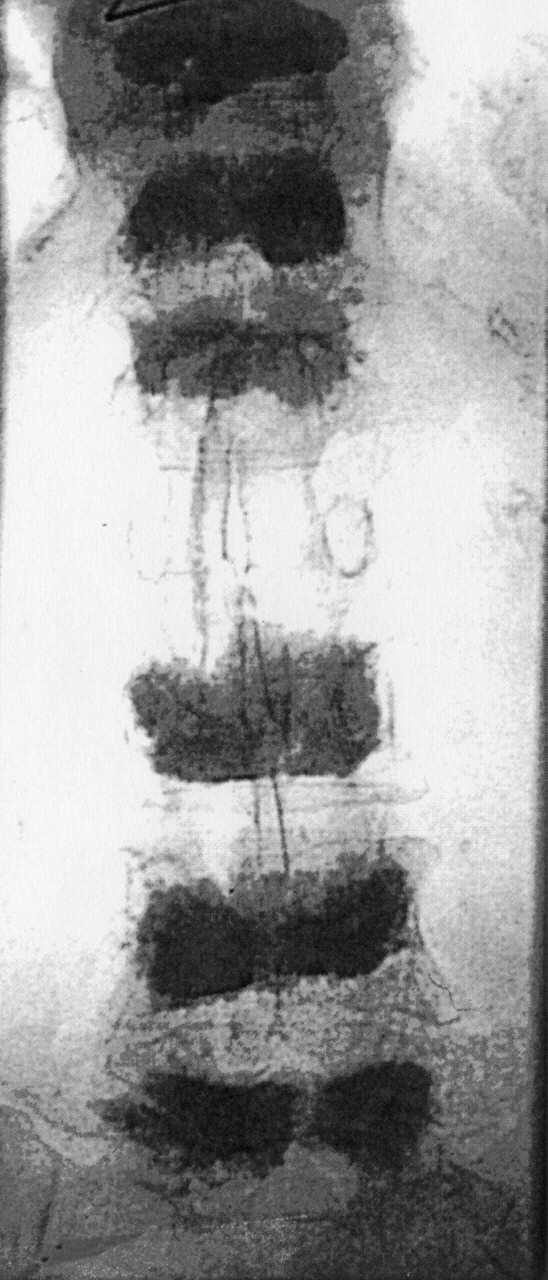
Anterioposterior radiograph showing six vertebrae treated with vertebroplasty. Ultimately, 10 levels were treated in this patient.
Similar articles
-
[Pelvic and leg venous thrombosis as a complication of percutaneous vertebroplasty].Rofo. 2003 Apr;175(4):565-6. doi: 10.1055/s-2003-38437. Rofo. 2003. PMID: 12677514 German. No abstract available.
-
Fluoroscopy-guided percutaneous vertebroplasty for symptomatic loosened pedicle screw and instrumentation-associated vertebral fracture: an evaluation of initial experiences and technical note.J Neurosurg Spine. 2018 Apr;28(4):364-371. doi: 10.3171/2017.7.SPINE17625. Epub 2018 Jan 12. J Neurosurg Spine. 2018. PMID: 29327973
-
Vertebroplasty of the first sacral vertebra.Pain Physician. 2009 May-Jun;12(3):651-7. Pain Physician. 2009. PMID: 19461832
-
Current concepts and techniques in percutaneous vertebroplasty.Orthop Clin North Am. 2006 Jul;37(3):409-34, vii. doi: 10.1016/j.ocl.2006.05.001. Orthop Clin North Am. 2006. PMID: 16846770 Review.
-
Percutaneous vertebroplasty: an update.Semin Ultrasound CT MR. 2005 Apr;26(2):52-64. doi: 10.1053/j.sult.2005.02.002. Semin Ultrasound CT MR. 2005. PMID: 15856807 Review.
Cited by
-
Transpedicle body augmenter in painful osteoporotic compression fractures.Eur Spine J. 2007 May;16(5):589-98. doi: 10.1007/s00586-006-0197-6. Epub 2006 Sep 7. Eur Spine J. 2007. PMID: 16957946 Free PMC article.
-
Image-Guided Bone Consolidation in Oncology.Semin Intervent Radiol. 2018 Oct;35(4):221-228. doi: 10.1055/s-0038-1669468. Epub 2018 Nov 5. Semin Intervent Radiol. 2018. PMID: 30402004 Free PMC article. Review.
-
Current perspectives on percutaneous vertebroplasty: current evidence/controversies, patient selection and assessment, and technique and complications.Radiol Res Pract. 2011;2011:175079. doi: 10.1155/2011/175079. Epub 2011 May 21. Radiol Res Pract. 2011. PMID: 22091375 Free PMC article.
-
Chronic obstructive pulmonary disease (COPD) patients with osteoporotic vertebral compression fractures (OVCFs): improvement of pulmonary function after percutaneous vertebroplasty (VTP).Eur Radiol. 2014 Jul;24(7):1577-85. doi: 10.1007/s00330-014-3165-2. Epub 2014 Apr 18. Eur Radiol. 2014. PMID: 24744201
-
Pulmonary cement embolisation after percutaneous vertebroplasty.BMJ Case Rep. 2023 Feb 2;16(2):e254292. doi: 10.1136/bcr-2022-254292. BMJ Case Rep. 2023. PMID: 36731953 Free PMC article. No abstract available.
References
-
- Deramond H, Depriester C, Galibert P, et al. Percutaneous vertebroplasty with PMMA: technique, indications and results. Radiol Clin North Am 1998;36:533–546 - PubMed
-
- Cotton A, Dewatre F, Cortet B, et al. Percutaneous vertebroplasty for osteolytic metastases and myeloma: effects of the percentage of lesion filling and the leakage of methyl methacrylate at clinical follow-up. Radiology 1996;200:525–530 - PubMed
-
- Kaplan FS, Scherl JD, Wisneski R, et al. The cluster phenomenon in patients who have multiple vertebral compression fractures. Clin Orthop 1993;297:161–167 - PubMed
MeSH terms
Substances
LinkOut - more resources
Full Text Sources
Medical