. 2004 Jan;123(1):5-19.
doi: 10.1085/jgp.200308918. Epub 2003 Dec 15.

Changes in local S4 environment provide a voltage-sensing mechanism for mammalian hyperpolarization-activated HCN channels

Affiliations

Changes in local S4 environment provide a voltage-sensing mechanism for mammalian hyperpolarization-activated HCN channels

Damian C Bell et al. J Gen Physiol. 2004 Jan.

Abstract

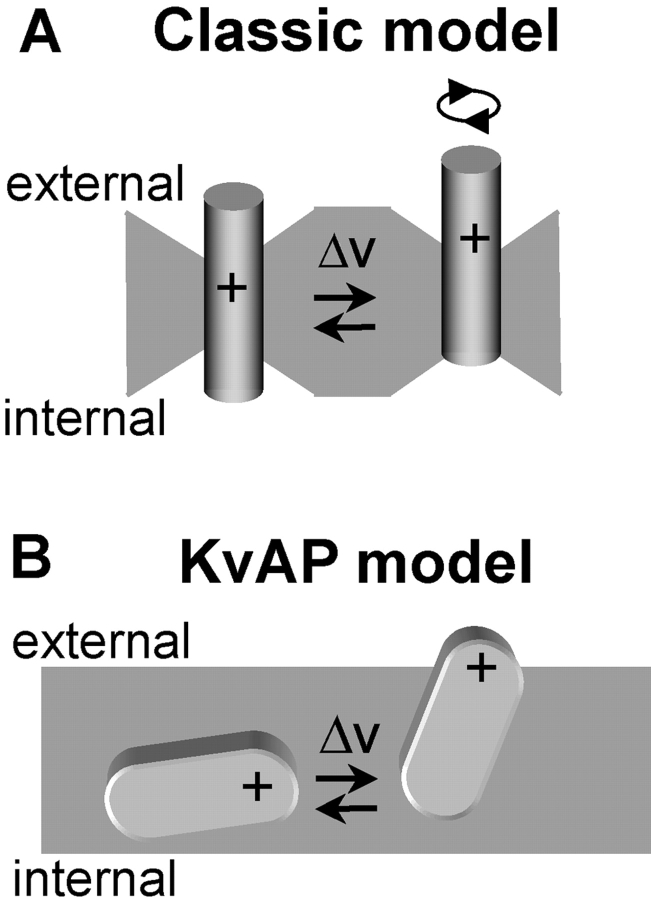
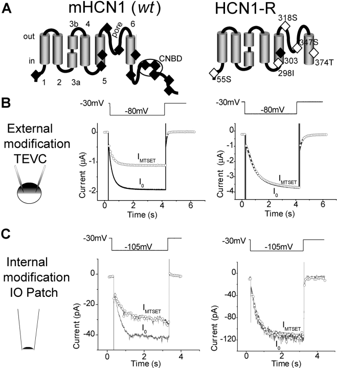
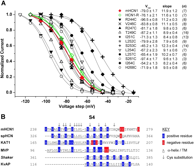
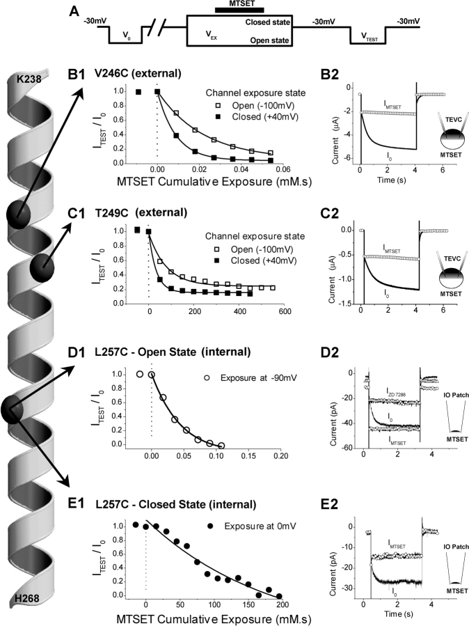
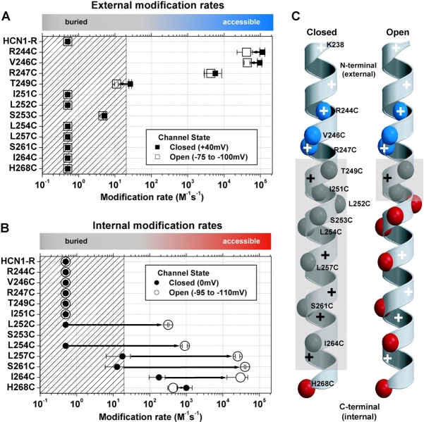
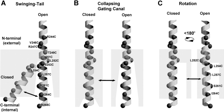
The positively charged S4 transmembrane segment of voltage-gated channels is thought to function as the voltage sensor by moving charge through the membrane electric field in response to depolarization. Here we studied S4 movements in the mammalian HCN pacemaker channels. Unlike most voltage-gated channel family members that are activated by depolarization, HCN channels are activated by hyperpolarization. We determined the reactivity of the charged sulfhydryl-modifying reagent, MTSET, with substituted cysteine (Cys) residues along the HCN1 S4 segment. Using an HCN1 channel engineered to be MTS resistant except for the chosen S4 Cys substitution, we determined the reactivity of 12 S4 residues to external or internal MTSET application in either the closed or open state of the channel. Cys substitutions in the NH2-terminal half of S4 only reacted with external MTSET; the rates of reactivity were rapid, regardless of whether the channel was open or closed. In contrast, Cys substitutions in the COOH-terminal half of S4 selectively reacted with internal MTSET when the channel was open. In the open state, the boundary between externally and internally accessible residues was remarkably narrow (approximately 3 residues). This suggests that S4 lies in a water-filled gating canal with a very narrow barrier between the external and internal solutions, similar to depolarization-gated channels. However, the pattern of reactivity is incompatible with either classical gating models, which postulate a large translational or rotational movement of S4 within a gating canal, or with a recent model in which S4 forms a peripheral voltage-sensing paddle (with S3b) that moves within the lipid bilayer (the KvAP model). Rather, we suggest that voltage sensing is due to a rearrangement in transmembrane segments surrounding S4, leading to a collapse of an internal gating canal upon channel closure that alters the shape of the membrane field around a relatively static S4 segment.


Figures

F<sc>igure</sc> 1.
Figure 1.
Models of voltage sensor movement during changes in membrane voltage. (A) A model for depolarization-activated channels (classic model). For clarity, a single S4 α-helix is shown which sits in a water-filled crevice with a narrow constriction, separating the internal from external environment. In response to membrane depolarization, S4 moves outward, causing translocation of a series of positively charged residues either by translation or rotation. (B) In the KvAP model, a voltage sensor paddle (formed of S3b-S4 helixes; one of four in the channel complex) moves through the lipid bilayer.
F<sc>igure</sc> 2.
Figure 2.
MTSET effects on wild-type mHCN1 and HNC1-R. (A) mHCN1 (wt) channel schematic (left) depicting the six transmembrane segment topology and COOH-terminal cyclic nucleotide–binding domain. S3 is divided into two regions (S3a and S3b) by a conserved proline break (Li-Smerin et al., 2000; Jiang et al., 2003a). 12 endogenous Cys are shown (filled diamonds). The right panel shows HCN1-R, with a COOH-terminal deletion and conservative mutations that removed five of six remaining Cys (open diamonds). Mutations at C303 were not possible without loss of functional expression (filled diamond). (B) The effect of external application of MTSET (5 mM for 2 min) on mHCN1 wt (left) and HCN1-R (right) channels. Currents were recorded using two-electrode voltage clamp (TEVC) by stepping from a holding voltage of −30 mV to a test voltage of −80 mV for 4 s, once every 15 s (voltage pulse protocol above current traces). Current traces are shown before MTSET application (I0, black line) and after washout of MTSET (IMTSET, open circles). (C) Effect of internal MTSET application (5 mM applied for 2 min) on mHCN1 wt (left) and HCN1-R (right) currents in cell-free inside-out patches. Currents were elicited by hyperpolarizing voltage steps (3-s duration) from a holding voltage of −30 mV to a test voltage of −105 mV. Current symbols as in B.
F<sc>igure</sc> 3.
Figure 3.
S4 voltage sensor Cys substitutions. (A) Mean, normalized tail current activation curves for mHCN1 wt (red, filled diamonds), HCN1-R (green, open diamonds), and the 12 Cys substitution mutant channels (see legend inset). Tail currents were fitted by a Boltzmann equation (see materials and methods) to obtain V1/2 and slope factor (mean ± SEM, both in mV, see legend inset); italicized figures in brackets are the number of experiments (n) for each channel. Boltzmann fits to mHCN1 and HCN1-R currents are shown as red and green lines, respectively; fits to Cys substitution mutant channels shown as thin, black lines. (B) Sequence alignment of S4 regions for selected hyperpolarization- and depolarization-activated K+ channels. The first four sequences are of hyperpolarization-activated channels: mouse HCN1 (used in this study, Santoro et al., 1997), sea urchin spHCN (Gauss et al., 1998), plant KAT1 (Anderson et al., 1992; Sentenac et al., 1992), and archaebacterial MVP (Sesti et al., 2003). The final two sequences are from depolarization-activated K+ channels: Drosophila Shaker (Kamb et al., 1987) and archaebacterial KvAP (Ruta et al., 2003). Residue numbering is at the NH2- and COOH-terminal end of each sequence; blue highlights positively charged residues (R or K); red highlights negatively charged residues (D or E); underlined residues form S4 transmembrane segment; arrows above mHCN1 indicate Cys substitution residues studied here. Alignments were adjusted so that residues responsible for gating charge movements of R362, R365, R368, and R371 for Shaker (Baker et al., 1998), and R117, R120, R123, and R126 for KvAP (Jiang et al., 2003b), were aligned with residues in mHCN1 we propose to be important for charge movement.
F<sc>igure</sc> 4.
Figure 4.
Effects of MTSET on three representative Cys substitution mutant channels: V246C, T249C, and L257C. The α-helical diagram representing mHCN1 S4 from K238 to H268 (far left) shows positions of the α-carbons (dark gray spheres) of the three residues described in this figure. (A) The voltage pulse protocol used for measuring effects of MTSET application to the channel in either the open or closed state (see materials and methods for details). (B and C) Effect of external application of MTSET on V246C (B1, B2) or T249C (C1, C2) currents measured using TEVC. (B1 and C1) Plot of normalized steady-state Ih current amplitude, ITEST/I0, as function of MTSET exposure time multiplied by MTSET concentration (units of mM·s) for applications to either the open state (open squares) or closed state (filled squares) of the channel. Note the 10,000-fold difference in cumulative exposure scale between B1 and C1. (B2 and C2) Current traces from individual experiments showing steady-state effects of external MTSET application to closed state of channel. Currents before (I0, black line) and after MTSET (IMTSET, open circles), show effect of external MTSET to inhibit Ih. (D and E) Effect on L257C channels in inside-out patches of cumulative exposure to internal MTSET applied to either open (D1) or closed (E1) states. Note the 1,000-fold difference in the cumulative exposure between D1 and E1. (D2) Open state MTSET modification caused channels to open constitutively (IMTSET, open circles), generating a large instantaneous “leakage” current that was blocked by ZD 7288 (50 μM, IZD 7288, open triangles). (E2) Closed state modification of L257C (IMTSET, open circles) had the opposite action, inhibiting channel opening.
F<sc>igure</sc> 5.
Figure 5.
A summary of external (A) and internal (B) MTSET second order reaction rates for HCN1-R and each of the Cys substitution mutant channels for both closed state (filled symbols) and open state (open symbols) exposure. Mean ± SEM reaction rates (3–6 experiments) were plotted on a Log10 scale for each Cys substitution mutant. The fastest modification rate on each graph (2.12 × 10⁵ s−1M−1) defines the reaction rate of MTSET with free sulfhydryls in aqueous solution (Pascual and Karlin, 1998). The hatched area on each plot represents modification rates that are ≤20 s−1M−1, a conservative guide-line based on the range of reactivity for Cys substitutions buried in the interior of globular proteins (∼50 s−1M−1, A. Karlin, personal communication). Colored bars at the top of each plot highlight this accessibility/buried definition: gray corresponds to buried Cys substitutions; blue corresponds to externally accessible Cys residues; red corresponds to internally accessible Cys substitutions. We arbitrarily assigned a modification rate of 0.5 s−1M−1, our lower limit of detection, to residues that failed to show significant reactivity (see materials and methods). (C) α-Helical diagrams summarizing the reactivity of Cys substitutions. Each of the α-carbons of the Cys substitutions are color-coded according to their accessibility as above. The gray, semiopaque areas delineate the region of the S4 α-helix that is protein and/or lipid buried. Positively charged residues are highlighted by plus symbols: black and white plus symbols indicate buried or accessible residues, respectively.
F<sc>igure</sc> 6.
Figure 6.
Three models for conformational changes in HCN1-R S4 region during channel gating based on MTSET-reactivity experiments. (A) Swinging-tail model, the COOH-terminal tail of S4 is buried within the lipid or protein interface (gray, semi-opaque area) in the closed state and swings into an aqueous environment in the open state. (B) Collapsing gating canal model, an extensive aqueous crevice collapses around and buries the COOH-terminal tail of S4 in the closed state. In the open state the crevice is open. (C) Rotation model, channel opening is associated with an ∼180° rotation of the COOH terminal tail of S4 that exposes one face of the α-helix that is buried within the membrane in the closed state.

Comment in

References

    1. Aggarwal, S.K., and R. MacKinnon. 1996. Contribution of the S4 segment to gating charge in the Shaker K+ channel. Neuron. 16:1169–1177. - PubMed
    1. Akabas, M.H., D.A Stauffer, M. Xu, and A. Karlin. 1992. Acetylcholine receptor channel structure probed in cysteine-substitution mutants. Science. 258:307–310. - PubMed
    1. Anderson, J.A., S.S. Huprikar, L.V. Kochian, W.J. Lucas, and R.F. Gaber. 1992. Functional expression of a probable Arabidopsis thaliana potassium channel in Saccharomyces cerevisiae. Proc. Natl. Acad. Sci. USA. 89:3736–3740. - PMC - PubMed
    1. Baker, O.S., H.P. Larsson, L.M. Mannuzzu, and E.Y. Isacoff. 1998. Three transmembrane conformations and sequence-dependent displacement of the S4 domain in shaker K+ channel gating. Neuron. 20:1283–1294. - PubMed
    1. Bezanilla, F. 2000. The voltage sensor in voltage-dependent ion channels. Physiol. Rev. 80:555–592. - PubMed

Publication types

Substances