

Review
doi: 10.1016/j.ohc.2003.12.001.
Anterior segment imaging: ultrasound biomicroscopy
Affiliations
- PMID: 15102510
- PMCID: PMC1978090
- DOI: 10.1016/j.ohc.2003.12.001
Item in Clipboard
Review
Anterior segment imaging: ultrasound biomicroscopy
Ophthalmol Clin North Am.
2004 Mar.
Abstract
Ultrasound biomicroscopy technology has become an indispensable tool in qualitative and quantitative assessment of the anterior segment. Advances in soft-ware design and algorithms will improve theoretical understanding of the pathophysiology of anterior segment disorders. Future applications of quantitative techniques will yield important information regarding mechanisms of angle closure, improving understanding of the dynamic functions of the iris,accommodation, presbyopia, and other aspects of anterior segment physiology and pathophysiology.
Figures
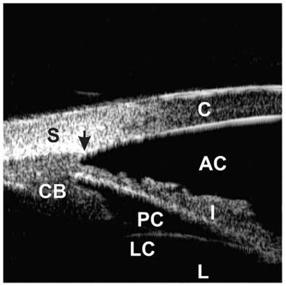
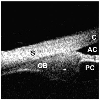
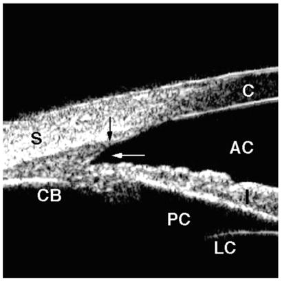
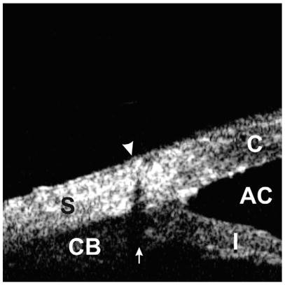
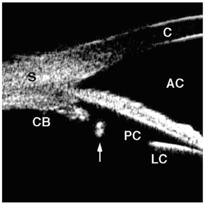
Ultrasound biomicroscopic appearance of a normal eye. The cornea (C), sclera (S), anterior chamber (AC), posterior chamber (PC), iris (I), ciliary body (CB), lens capsule (LC), and lens (L) can be identified. The scleral spur (black arrow) is an important landmark to assess the morphologic relationships among the anterior segment structures.
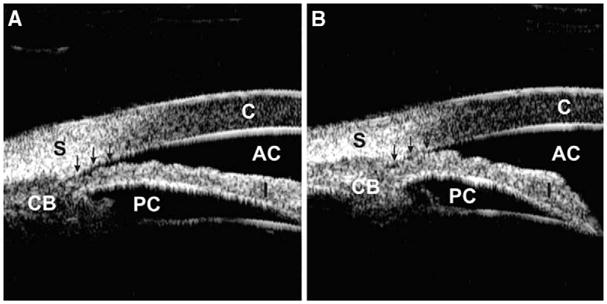
Occludable angle with dark room provocative test. (A) The anterior chamber angle is slit-like opened (arrows) under a lighted condition. (B) The angle is completely occluded (arrows) under a dark condition.
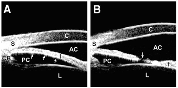
Pupillary block. (A) The angle shows appositional closure owing to anterior bowing (arrows) of the iris. (B) The angle is open with a flattened iris after laser peripheral iridotomy. The patent hole on the iris (arrow) equalizes the pressure between the anterior and posterior chambers.
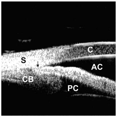
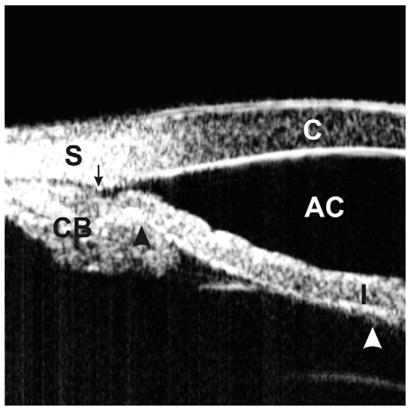
Plateau iris. A large and anteriorly positioned ciliary body holds the iris root up against the cornea, leading to a partially occluded angle. The arrow represents the location of the scleral spur.
Indentation UBM on an eye with a plateau iris. The angle is slit-like opened (the arrow represents the scleral spur location). The “double-hump” sign, one hump owing to the ciliary process (black arrow head) and the other owing to the lens (white arrow head), is demonstrated. (Adapted from Ishikawa H, Inazumi K, Liebmann JM, Ritch R. Inadvertant corneal indentation can cause artifactitious widening of the iridocorneal angle on ultrasound biomicroscopy. Ophthalmic Surg Lasers 2000;31(4):342 – 5; with permission.)
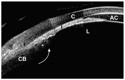
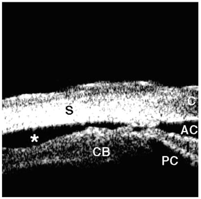
Malignant glaucoma (composite image). The lens, iris, and ciliary process are all pushed forward, resulting in an extremely shallow anterior chamber and totally occluded angle. The ciliary process (asterisk) is completely anteriorly rotated (white arrow), probably pulled by zonules. The scleral spur is located at the black arrow.
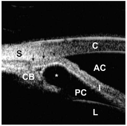
Angle closure owing to an iridociliary cyst. An iridociliary cyst (asterisk) pushes the iris root toward the cornea, resulting in total occlusion of the angle (arrows).
Pigment dispersion syndrome. The angle is wide with a concave iris (arrow). Note the extremely wide iridolenticular contact. (Adapted from Breingan PJ, Esaki K, Ishikawa H, et al. Iridolenticular contact decreases following laser iridotomy for pigment dispersion syndrome. Arch Ophthalmol 1999;117(3):325–8; with permission.)
Iridociliary tumor. Abnormally large ciliary process (asterisk) involving the iris root and pars plana is visualized.
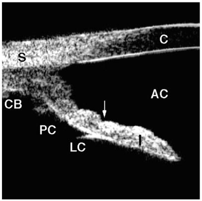
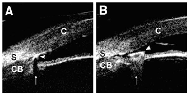
Angle recession. Blunt trauma caused a tear into the ciliary body face (white arrow), but the iris remained attached to the scleral spur (black arrow). There is no direct communication between the anterior chamber and the supraciliary space.
Cyclodialysis. The ciliary body is avulsed from the sclera, resulting in free aqueous flow from the anterior chamber through the cleft into the supraciliary space (asterisk).
Intraocular foreign body. (A) Foreign body (arrow head) with a material that consists of multiple cavities inside (ie, wood and concrete) generates shadowing artifact (arrow) by absorbing ultrasound power. The iris image is masked by shadowing. (B) Hard and dense foreign body (arrow head) (ie, glass and metal) creates comet tail artifact (arrow) owing to multiple internal reflections. The iris image is disrupted by the comet tail artifact. (Adapted from Laroche D, Ishikawa H, Greenfield D, et al. Ultrasound biomicroscopic localization and evaluation of intraocular foreign bodies. Acta Ophthalmol Scand 1998;76(4):491–5; with permission.)
Scleral suture can be identified by looking for its shadowing artifact (arrow). This artifact is created owing to refraction of the ultrasound beam at a boundary between suture thread and the surrounding tissues.
Posterior chamber intraocular lens haptic. The most peripheral portion of the haptic is positioned within the capsular bag and is located central to the ciliary process (arrow).
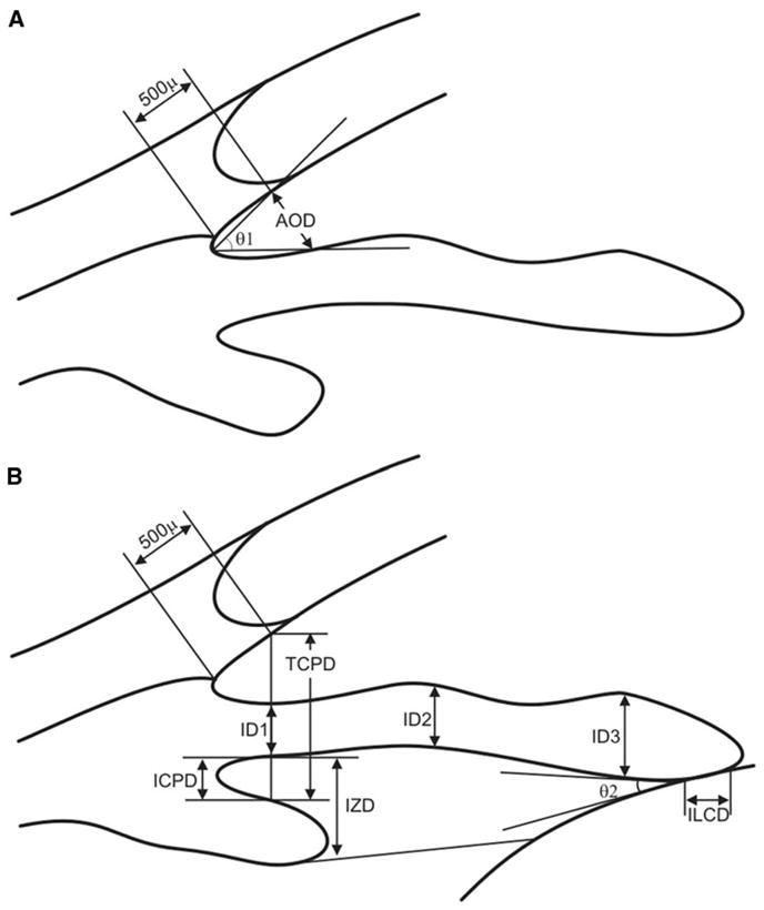
Pavlin’s measurement parameters (see Table 1). (A) The angle opening distance (AOD) is defined as the length of the line drawn from the point on the corneal endothelial surface 500 μm anterior to the scleral spur to the iris surface perpendicular to the corneal endothelial surface. The trabecular–iris angle (TIA, θ 1) is defined as an angle formed with the apex at the iris recess and the arms passing through the point on the meshwork 500 μm from the scleral spur and the point on the iris perpendicularly opposite. (B) The trabecular ciliary distance (TCPD) is defined as the distance between a point 500 μm from the scleral spur and the ciliary process on the line that is perpendicular through the iris. The iris thickness (ID1) is defined along this line, as is the iris–ciliary process distance (ICPD). Iris thickness also can be measured 2 mm from the iris root (ID2) and at its thickest point near the margin (ID3). The iris–zonule distance (IZD) is defined as a part of theTCPD at a point just clearing the ciliary process. The length of iris–lens contact (ILCD) and the angle at which the iris leaves the lens surface (iris–lens angle; ILA, θ 2) are easily measured.
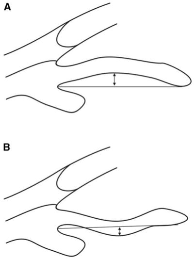
Iris concavity/convexity. Iris configuration is determined first by creating a line from the most peripheral to the most central points of iris pigment epithelium. A perpendicular line is then extended from this line to the iris pigment epithelium at the point of greatest concavity or convexity. (A) Iris convexity measurement (arrow). (B) Iris concavity measurement (arrow).
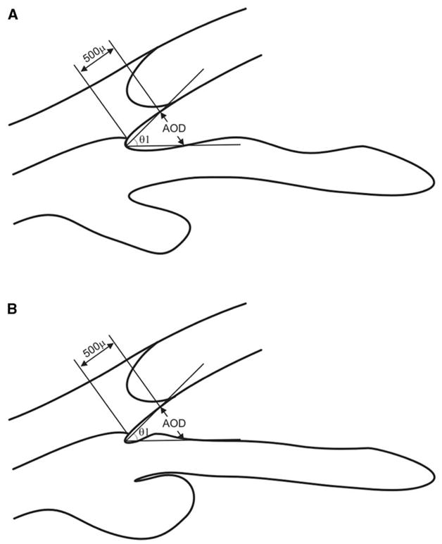
Limitation of the conventional angle opening distance (AOD) measurement. (A) and (B) have exactly the same value for the AOD and trabecular–iris angle (TIA, θ 1). Nevertheless, the angle in (B) is gonioscopically narrower and is more likely to be occludable than the normal-appearing angle in (A).
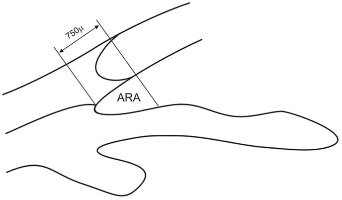
Angle recess area (ARA). The ARA is defined as a triangular area bordered by the anterior iris surface, corneal endothelium, and a line perpendicular to the corneal endothelium drawn from a point 750 μm anterior to the scleral spur to the iris surface.
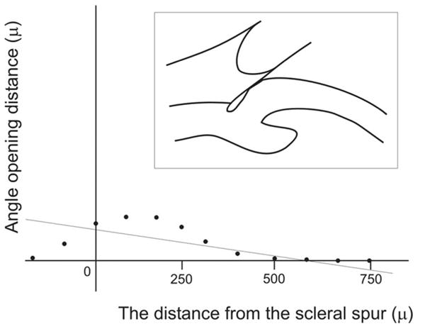
Negative acceleration in ARA analysis. The linear regression analysis of ARA shows negative acceleration, meaning that the angle almost has a normal configuration at its peripheral part and becomes very shallow or is apposed to the cornea at its central part (ie, the appositional angle closure began at the level of Schwalbe’s line).
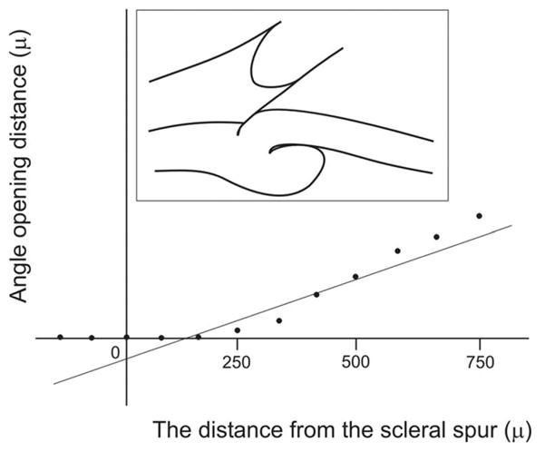
Negative y-intercept in ARA analysis. The linear regression analysis shows a negative y-intercept, indicating that the angle recess is very shallow or is attached to the cornea at its periphery, whereas it has a relatively wide angle recess centrally (ie, plateau iris and synechial closure).
References
-
- Pavlin CJ, Harasiewicz K, Foster FS. Ultrasound biomicroscopy of anterior segment structures in normal and glaucomatous eyes. Am J Ophthalmol. 1992;113:381–9. - PubMed
-
- Pavlin CJ, Sherar MD, Foster FS. Subsurface ultrasound microscopic imaging of the intact eye. Ophthalmology. 1990;97:244–50. - PubMed
-
- Pavlin CJ, Harasiewicz K, Sherar MD, et al. Clinical use of ultrasound biomicroscopy. Ophthalmology. 1991;98:287–95. - PubMed
-
- Tello C, Potash S, Liebmann J, et al. Soft contact lens modification of the ocular cup for high-resolution ultrasound biomicroscopy. Ophthalmic Surg. 1993;24:563–4. - PubMed
-
- Tello C, Liebmann JM, Ritch R. An improved coupling medium for ultrasound biomicroscopy. Ophthalmic Surg. 1994;25:410–1. - PubMed
Publication types
MeSH terms
Grants and funding
LinkOut - more resources
Full Text Sources
Other Literature Sources
