

Three-dimensional model of the feline hindlimb
- PMID: 15164372
- PMCID: PMC2043500
- DOI: 10.1002/jmor.10233
Three-dimensional model of the feline hindlimb
Abstract
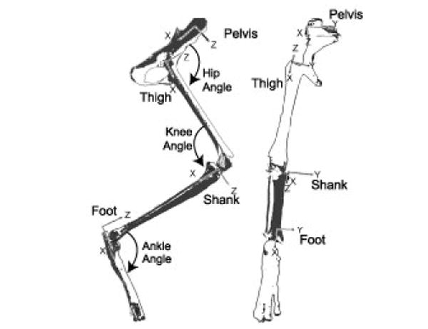
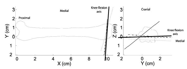
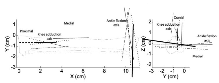
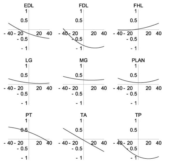
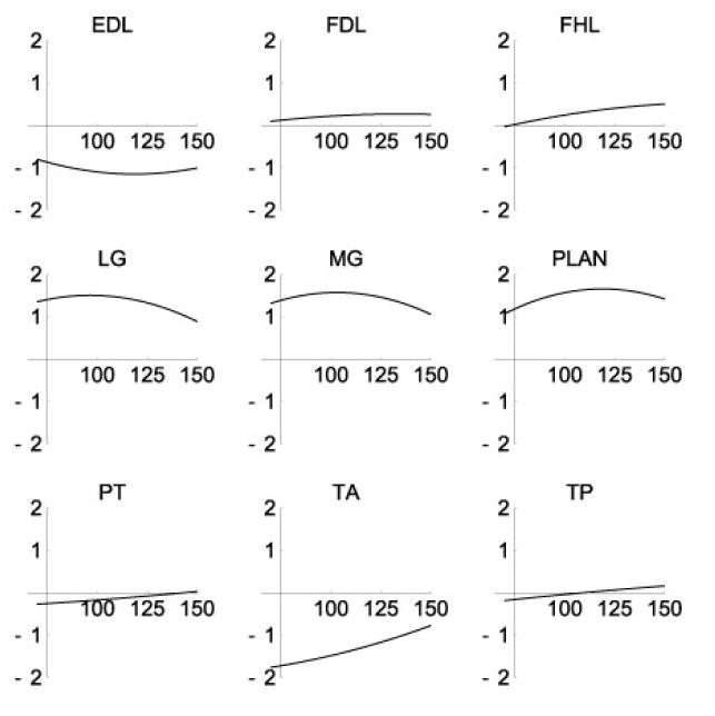
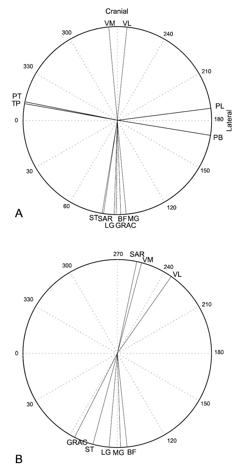
This article describes a three-dimensional musculoskeletal model of the feline hindlimb based on digitized musculoskeletal anatomy. The model consists of seven degrees of freedom: three at the hip and two each at the knee and ankle. Lines of action and via points for 32 major muscles of the limb are described. Interspecimen variability of muscle paths was surprisingly low; most via points displayed a scatter of only a few millimeters. Joint axes identified by mechanical techniques as noncoincident and nonorthogonal were further honed to yield moment arms consistent with previous reports. Interspecimen variability in joint axes was greater than that of muscle paths and highlights the importance of joint axes in kinematic models. The contribution of specific muscles to the direction of endpoint force generation is discussed.
Copyright 2004 Wiley-Liss, Inc.
Figures
Similar articles
-
Muscle moment arms of the gibbon hind limb: implications for hylobatid locomotion.J Anat. 2010 Apr;216(4):446-62. doi: 10.1111/j.1469-7580.2009.01209.x. J Anat. 2010. PMID: 20447251 Free PMC article.
-
Inter-joint coupling effects on muscle contributions to endpoint force and acceleration in a musculoskeletal model of the cat hindlimb.J Biomech. 2007;40(16):3570-9. doi: 10.1016/j.jbiomech.2007.06.001. Epub 2007 Jul 20. J Biomech. 2007. PMID: 17640652 Free PMC article.
-
Probabilistic modeling of knee muscle moment arms: effects of methods, origin-insertion, and kinematic variability.Ann Biomed Eng. 2007 Sep;35(9):1632-42. doi: 10.1007/s10439-007-9334-6. Epub 2007 Jun 2. Ann Biomed Eng. 2007. PMID: 17546504
-
A three dimensional multiplane kinematic model for bilateral hind limb gait analysis in cats.PLoS One. 2018 Aug 6;13(8):e0197837. doi: 10.1371/journal.pone.0197837. eCollection 2018. PLoS One. 2018. PMID: 30080884 Free PMC article.
-
Kinematic models of lower limb joints for musculo-skeletal modelling and optimization in gait analysis.J Biomech. 2017 Sep 6;62:77-86. doi: 10.1016/j.jbiomech.2017.04.029. Epub 2017 May 22. J Biomech. 2017. PMID: 28601242 Review.
Cited by
-
Optimization of muscle activity for task-level goals predicts complex changes in limb forces across biomechanical contexts.PLoS Comput Biol. 2012;8(4):e1002465. doi: 10.1371/journal.pcbi.1002465. Epub 2012 Apr 12. PLoS Comput Biol. 2012. PMID: 22511857 Free PMC article.
-
Motoneuron intrinsic properties, but not their receptive fields, recover in chronic spinal injury.J Neurosci. 2013 Nov 27;33(48):18806-13. doi: 10.1523/JNEUROSCI.2609-13.2013. J Neurosci. 2013. PMID: 24285887 Free PMC article.
-
Estimation of musculoskeletal models from in situ measurements of muscle action in the rat hindlimb.J Exp Biol. 2011 Mar 1;214(Pt 5):735-46. doi: 10.1242/jeb.049163. J Exp Biol. 2011. PMID: 21307059 Free PMC article.
-
Practical limits on muscle synergy identification by non-negative matrix factorization in systems with mechanical constraints.Med Biol Eng Comput. 2013 Feb;51(1-2):187-96. doi: 10.1007/s11517-012-0983-8. Epub 2012 Nov 3. Med Biol Eng Comput. 2013. PMID: 23124815 Free PMC article.
-
EFFECTS OF SPINAL TRANSECTION AND LOCOMOTOR SPEED ON MUSCLE SYNERGIES OF THE CAT HINDLIMB.bioRxiv [Preprint]. 2024 Sep 20:2024.09.19.613891. doi: 10.1101/2024.09.19.613891. bioRxiv. 2024. Update in: J Physiol. 2025 May;603(10):3061-3088. doi: 10.1113/JP288089. PMID: 39345603 Free PMC article. Updated. Preprint.
References
-
- An KN, Takahashi K, Harrigan TP, Chao EY. Determination of muscle orientations and moment arms. J Biomech Eng. 1984;106:280–282. - PubMed
-
- Bizzi E. Motor control mechanisms. An overview. Neurol Clin. 1987;5:523–528. - PubMed
-
- Burkholder TJ, Lieber RL. Sarcomere length operating range of vertebrate muscles during movement. J Exp Biol. 2001;204:1529–1536. - PubMed
-
- Carro LP, Garcia MS, Gracia CS. Bifurcate popliteus tendon. Arthroscopy. 1999;15:638–9. - PubMed
-
- Ceyhan O, Mavt A. Distribution of agenesis of palmaris longus muscle in 12 to 18 years old age groups. Indian J Med Sci. 1997;51:156–60. - PubMed
Publication types
MeSH terms
Grants and funding
LinkOut - more resources
Full Text Sources
