Review
. 2004 Jun;123(6):643-56.
doi: 10.1085/jgp.200409089.

The sliding filament model: 1972-2004

Review

The sliding filament model: 1972-2004

Roger Cooke. J Gen Physiol. 2004 Jun.
No abstract available


Figures

F<sc>igure</sc> 1.
Figure 1.
The structure of the head region of myosin, determined by Rayment et al. (1993b). The catalytic domain is shown on the left. The upper 50K, lower 50K, nucleotide binding, and converter domains are colored red, white, green, and blue respectively. The relay helix is colored blue with its distal end connected to the actin binding side in the lower 50K domain by a blue strand, shown at the top of he molecule.
F<sc>igure</sc> 2.
Figure 2.
The lever arm movement of the light chain domain. Reconstructions of the actin–myosin complex at the beginning and end of the power stroke. (A) The “beginning” of the power stroke, based on the truncated S1–ADP.vanadate coordinates (PDB-1VOM). The missing lever arm has been restored using the chicken S1 coordinates (PDB-MYS) with an appropriate rotation. The break in the chain at the beginning of the lever arm marks the extent of the fragment of S1 used in the crystal structure analysis. (B) The “end” state, or rigor complex. Note that the end of the lever arm moves ∼12 nm between the two states. Regions of myosin are colored as in Fig. 1, with the exception that the colors of the light chains have been switched. Diagram prepared with GRASP (Nicholls et al., 1991). Reproduced with permission from Holmes (1997).
F<sc>igure</sc> 3.
Figure 3.
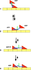
A schematic of the actomyosin cycle. In state 1 the myosin has just been released from actin and is in the post power stroke conformation. In the transition from state 1 to 2, nucleotide hydrolysis promotes the transition to the prepower stroke conformation, although the coupling between nucleotide state and conformation is not tight, with rapid interconversion between conformations and nucleotide states occurring between States 2 and 3. Myosin then binds weakly to actin in State 3. Subsequent release of phosphate leads to a stronger bond in State 4. State 3 probably has multiple substates, some force generating and some not. In State 4 the myosin is strongly bound to actin, with a rigid conformation that represents the end of the power stroke. An important aspect of the cycle that is omitted in the cartoon, is that the molecules are in constant motion, undergoing energetic Brownian motions in times of micro- to milliseconds.
F<sc>igure</sc> 4.
Figure 4.
A schematic of the kinesin microtubule interaction. In State 1 the microtubule bound head has no bound nucleotide, and the unattached head has just been released from the trailing site on the microtubule in the transition from State 4 to 1. The binding of ATP to the bound head in State 2 promotes docking of the neck linker along one side of the motor domain, as shown by the straight blue line. This positions the unbound head toward the plus end of the microtubule, toward which the kinesin is walking. However, the free energy favoring docking is small and docked and undocked conformations are in rapid equilibrium. The binding of the kinesin head to the microtubule in State 3 leads to a stable configuration, and produces an effective step of ∼4 nm. The release of phosphate from the trailing head leads to undocking of the neck linker, whose random coil configuration produces a large force between the heads, releasing the trailing head. State 4 then transitions back to State 1, having move 8 nm to the right. When viewing this figure the reader should remember that the molecules are undergoing constant Brownian motions.
F<sc>igure</sc> 5.
Figure 5.
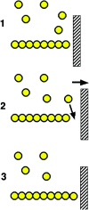
A schematic of force production by actin polymerization. A single actin polymer is shown adjacent to a load, against which it is pushing. In the transition from State 1 to 2 the gap between the end of the filament and the load is increased by either a fluctuation in the position of the load, or in the position of the actin filament. This allows the insertion of an additional actin monomer, thus extending the filament, and leading to a new equilibrium position that has moved 2.7 nm to the right in State 3.
F<sc>igure</sc> 6.
Figure 6.
The first model of a motor protein, proposed by Sir Andrew Huxley in 1957, before the myosin cross-bridge had been visualized. The myosin is shown connected to the filament backbone by two springs. As shown, a thermal fluctuation has moved the myosin part of the way toward the actin site, which is entering from the right. A further fluctuation can carry it the rest of the distance, where binding to actin traps the springs in distorted positions. Relaxation of the springs then drags the actin to the left. When the actin myosin positions reach the center, where both springs are in their relaxed positions, rapid binding of ATP releases the myosin from actin. A similar cyclic interaction between motors and polymers, orchestrated by the binding of nucleotides is thought to produce the motility of both actin-myosin and kinesin-microtubule motor systems.

Similar articles

Cited by

References

    1. Anson, M., M.A. Geeves, S.E. Kurzawa, and D.J. Manstein. 1996. Myosin motors with artificial lever arms. EMBO J. 15:6069–6074. - PMC - PubMed
    1. Baker, J.E., I. Brust-Mascher, S. Ramachandran, L.E. LaConte, and D.D. Thomas. 1998. A large and distinct rotation of the myosin light chain domain occurs upon muscle contraction. Proc. Natl. Acad. Sci. USA. 95:2944–2949. - PMC - PubMed
    1. Bray, D. 1972. Cytoplasmic Actin: A Comparative Study. Cold Spring Harbor Symposia on Quantitative Biology. The Cold Spring Laboratory, Cold Spring Harbor. XXXVII:567–571.
    1. Case, R., D. Pierce, N. HomBooher, C. Hart, and R. Vale. 1997. The directional preference of kinesin motors is specified by an element outside of the motor catalytic domain. Cell. 90:959–966. - PubMed
    1. Cooke, R. 1986. The mechanism of muscle contraction. CRC Crit. Rev. Biochem. 21:53–118. - PubMed