. 2004 Jul;87(1):714-27.
doi: 10.1529/biophysj.103.033993.

Determination of cell capacitance using the exact empirical solution of partial differential Y/partial differential Cm and its phase angle

Affiliations

Determination of cell capacitance using the exact empirical solution of partial differential Y/partial differential Cm and its phase angle

Joseph Santos-Sacchi. Biophys J. 2004 Jul.

Abstract

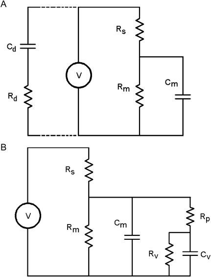
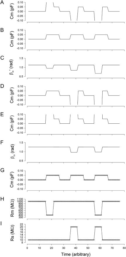
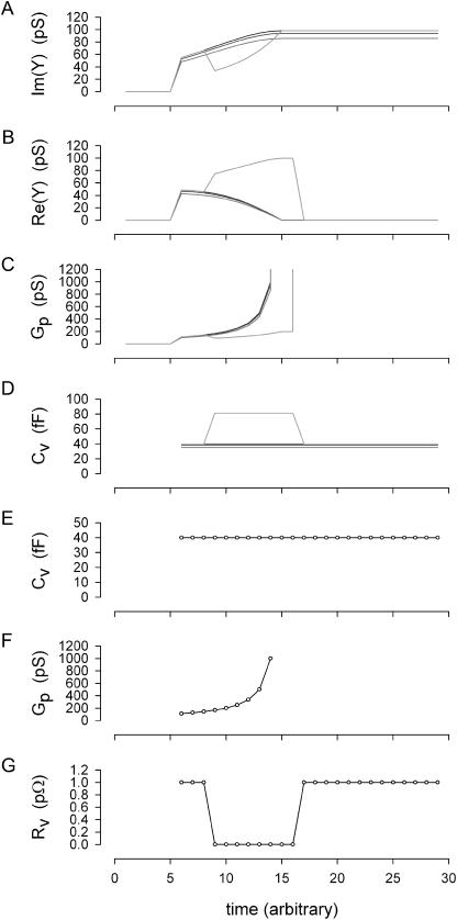
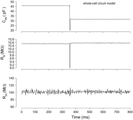
Measures of membrane capacitance offer insight into a variety of cellular processes. Unfortunately, popular methodologies rely on model simplifications that sensitize them to interference from inevitable changes in resistive components of the traditional cell-clamp model. Here I report on a novel method to measure membrane capacitance that disposes of the usual simplifications and assumptions, yet is immune to such interference and works on the millisecond timescale. It is based on the exact empirical determination of the elusive partial derivative, partial differential Y/partial differential C(m), which heretofore had been approximated. Furthermore, I illustrate how this method extends to the vesicle fusion problem by permitting the determination of partial differential Y(v)/partial differential C(v), thereby providing estimates of fusion pore conductance and vesicle capacitance. Finally, I provide simulation examples and physiological examples of how the method can be used to study processes that are routinely interrogated by measures of membrane capacitance.


Figures

FIGURE 1
FIGURE 1
Circuit models. (A) The standard patch-clamp-cell model. Voltage (V) is set across the electrode (Rs) and cell membrane resistance (Rm)—capacitance (Cm). The series components between headstage and ground, Rd and Cd, model the whole-cell capacitance compensation circuitry when connected. (B) A vesicle is fused with the plasma membrane. Cv is vesicle capacitance, Rp is fusion pore resistance, and Rv is vesicle resistance.
FIGURE 2
FIGURE 2
Simulation of capacitance changes in whole-cell mode. The component values of the model (Rs: 10 MΩ, Rm: 1 GΩ, and Cm: 6.5 pF) in Fig. 1 A were modulated out of phase with each other, with a Cm jump of 0.05 pF accompanied by either a 600-MΩ drop in Rm, or a 10-MΩ increase in Rs or all changes occurring simultaneously (see panels GI). The stimulating frequency f0 was the same for single-sine and eCm methods, with f0 at 390.6 Hz and f1 at twice that. In panels AC, calculations are based on setting the PSD angle to an estimate (denoted by the prime) of βω, the angle of ∂Y/∂Gs − 90°, formula image to mimic Rs dithering. (A) A true piecewise linear approach was employed using this angle formula image in place of βω in Eq. 52. Whole-cell capacitance compensation was modeled by connecting and supplying the circuit components Rd and Cd (Fig. 1) with corresponding values of Rs and Cm, but with an overall negative admittance. PSD angle and gain corrections (1/abs(∂Y/∂Cm) were determined from whole-cell conditions at the zero time point and remained fixed throughout. It can be seen that when cell components are changed (GI) the phase angle changes causing errors in Cm estimation (A). Even though the PSD angle is set to guard against Rs changes, a change from 10 to 20 MΩ (I) is too large to counter; such overpowering effects of parameter changes are well known (Lindau, 1991). However, if capacitance compensation is not employed and point-by-point resetting of new angle and gain factors are made and applied, absolute Cm is obtained without any errors (B). To make point-by-point corrections experimentally, the raw admittance (Y) at each point was taken and the angle of formula image was calculated according to Zierler (1992), namely, formula image The true gain factor, Hc, at each data point was calculated as 1/abs(∂Y/∂Cm). With each new gain and angle, circuit parameters were calculated as in Eq. 52, by extracting the component of Y at that phase angle and multiplying by that gain factor. Each admittance point was so treated to obtain circuit parameters. The reason this procedure works so well is that the value returned by this modified PSD analysis is the imaginary component of Y; thus, this method produces the same results as the eCm method as shown in panel G. This useful single-sine approach, employing the estimate of Hc provided by Gillis (1995), formula image is implemented in jClamp. However, because this is an estimate of the true gain, 1/abs(∂Y/∂Cm), relying on circuit approximations, Cm estimates are not fully immune from circuit parameter changes. In panels DF, calculations are based on setting the PSD angle to the angle of ∂Y/∂Cm, namely βω, to mimic capacitance compensation dithering. (D) The true piecewise linear approach was employed as above in panel A. In this case, using βω, the large change in Rm does not affect the phase angle substantially (F), so Cm estimates are accurate and robust. However, Rs changes do interfere with angle and estimate, as expected (Joshi and Fernandez, 1988). Unlike the treatment above (B), panel E shows that applying a point-by-point correction as detailed above to the uncompensated admittance fails to provide error free Cm estimation, because the imaginary component of Y is not returned in this case. Panels GI show the results of the eCm method, where the calculated absolute values are depicted by the circles. Note an exact correspondence between actual parameter values (solid lines) and calculated estimates (○), with no parameter interactions. Simulation in MatLab.
FIGURE 3
FIGURE 3
Simulation and analysis of vesicle fusion event. Whole-cell conditions remained constant throughout simulation at Rm: 1 GΩ, and Cm: 6.5 pF, with Rs: 1, 10, and 20 MΩ for dark traces (vesicle resistance, Rv, held constant at 1 pΩ (1e15Ω)). For the shaded trace, Rs was 1 MΩ and vesicle resistance, Rv, was stepped transiently from 1 pΩ to 10 GΩ as shown in panel G. (A, B) Imaginary and real components of admittance determined according to Breckenridge and Almers (1987). (C, D) Vesicle pore conductance and capacitance extracted from admittance using standard methodology (Breckenridge and Almers, 1987; Lollike et al., 1995). Note very good correspondence between components of model even when Rs changes substantially (solid lines in panels E, F), but not when Rv is altered (shaded line). This discrepancy is not unanticipated because the standard methodology sets Rv as infinite (Breckenridge and Almers, 1987; Lollike et al., 1995). (E, F) Vesicle model parameters (solid lines) and estimates made with the eCm method (○). Correspondence is exact under all conditions. At time >5, vesicular fusion was simulated by linearly ramping the fusion pore resistance (Rp; initially infinite) from 9 GΩ (111 pS) to 1 GΩ (1000 pS); the resulting pore conductance is shown in panel F (solid line). Fusion event analysis was implemented at that time.
FIGURE 4
FIGURE 4
Effects of large Cm changes on parameter estimates with the eCm method. Nominal initial component values of Rs: 10 MΩ, Rm: 100 MΩ, and Cm: 33 pF ‖ 15 pF. A step decrease in capacitance was accomplished by suddenly removing the parallel 15 pF component. The three panels show the calculated values of the parameters using the eCm method at a sampling rate of 2.56 ms. Note large abrupt drop in capacitance (top) with virtually no effect on measures of Rs and Rm (middle and bottom). Model was voltage clamped with a PC clone, Axon 200 amplifier (Union City, CA) in resistive feedback mode (β = 0.1), 10-kHz Bessel filter, and Axon 1322A A/D D/A board.
FIGURE 5
FIGURE 5
Effects of large Rm changes on parameter estimates with the eCm method. Nominal component values of Rs: 10 MΩ, Rm: 50 or 800 MΩ, and Cm: 15 pF. Note minimal interference with Cm and Rs estimates when a 50-MΩ resistor replaced the 800-MΩ resistor, other than changes in noise levels. PC clone, Axon 200 amplifier in capacitive feedback mode, 10-kHz Bessel filter, and Axon 1322A A/D D/A board were used.
FIGURE 6
FIGURE 6
Effects of uncompensated stray capacitance on Cm measures with the eCm method. (A) Capacitive currents evoked by voltage step. Model Rs was in headstage but ungrounded. (Top) Fully compensated, (middle) undercompensated, and (bottom) overcompensated. The effect of these extremes was evaluated during parameter estimations after reassembly of the model circuit. (B) The three panels show model cell parameter estimates during manual under- and overcompensation of fast capacitance compensation. Cm was modulated ±0.3%; Rs, ±1.8%; and Rm, < ±0.01%. The increase in Cm occurred during under compensation. Nominal component values of Rs: 10 MΩ, Rm: 300 MΩ, and Cm: 18 pF. Cm noise: 14.6 fF rms; system noise with model 3.75 pA rms, 10-kHz Bessel filter, PC clone, Axon 200 amplifier in capacitive feedback mode, and Axon 1322A A/D D/A board.
FIGURE 7
FIGURE 7
Measurement of outer hair cell nonlinear capacitance with the eCm method. The rapid relaxation in capacitance during a step voltage change is due to the shift of the cell's nonlinear Q-V function along the voltage axis (Santos-Sacchi et al., 1998), and was confirmed through alternative measures. Cell was clamped with a PC clone, Axon 200B amplifier, 10-kHz Bessel filter, and Axon 1321A A/D D/A board with conditions described previously (Santos-Sacchi et al., 1998). See text for further details.
FIGURE 8
FIGURE 8
Measurement of capacitance step in prestin transfected HEK cell. Under voltage clamp a step voltage from +50 mV to +30 mV evoked a step increase in capacitance of 30 fF. Cm noise: 5.5 fF rms. PC clone, Axon 200B amplifier in resistive feedback mode, 10-kHz Bessel filter, and National Instruments (Austin, TX) PCI-6052E A/D D/A board were used.
FIGURE 9
FIGURE 9
Effect of system noise on Cm estimate noise. Results from either mathematical modeling (lines) or physical modeling (symbols). Three methodologies, step (dashed line, ▾), eCm (dash-dotted line, ▴), and single-sine phase tracking (solid line, ▪) are presented. For the software model, forced Gaussian noise levels were imposed, and the noise of Cm estimates calculated. For the physical model, system noise levels were 3.8 pA rms when the model was attached to the headstage. To obtain lower system noise levels, averaging was performed to produce the plotted noise levels. For the electrical model, a 10-kHz Bessel filter was used, and the frequency components of the remaining noise were likely different from the wideband noise used for the math model. This likely accounts for differences in math and electrical model results. In any case, the data from each model indicate that as system noise decreases, all of the methods become comparable. Nominal component values of Rs: 10 MΩ, Rm: 300 MΩ, and Cm: 18 pF. IBM T40 laptop in battery mode (Armonk, NY), Axon 200 amplifier in capacitive feedback mode, 10-kHz Bessel filter, and Quatech (Hudson, OH) DAQP 308 PCMCIA PC card A/D D/A board were used.

Similar articles

Cited by

References

    1. Ales, E., L. Tabares, J. M. Poyato, V. Valero, M. Lindau, and D. T. Alvarez. 1999. High calcium concentrations shift the mode of exocytosis to the kiss-and-run mechanism. Nat. Cell Biol. 1:40–44. - PubMed
    1. Alvarez De Toledo, G. A., R. Fernandez-Chacon, and J. M. Fernandez. 1993. Release of secretory products during transient vesicle fusion. Nature. 363:554–558. - PubMed
    1. Aravanis, A. M., J. L. Pyle, and R. W. Tsien. 2003. Single synaptic vesicles fusing transiently and successively without loss of identity. Nature. 423:643–647. - PubMed
    1. Barnett, D. W., and S. Misler. 1997. An optimized approach to membrane capacitance estimation using dual-frequency excitation. Biophys. J. 72:1641–1658. - PMC - PubMed
    1. Bigiani, A., and S. D. Roper. 1995. Estimation of the junctional resistance between electrically coupled receptor cells in Necturus taste buds. J. Gen. Physiol. 106:705–725. - PMC - PubMed

Publication types

LinkOut - more resources