

Respiratory motion of the heart from free breathing coronary angiograms
- PMID: 15338737
- PMCID: PMC2494710
- DOI: 10.1109/TMI.2004.828676
Respiratory motion of the heart from free breathing coronary angiograms
Abstract
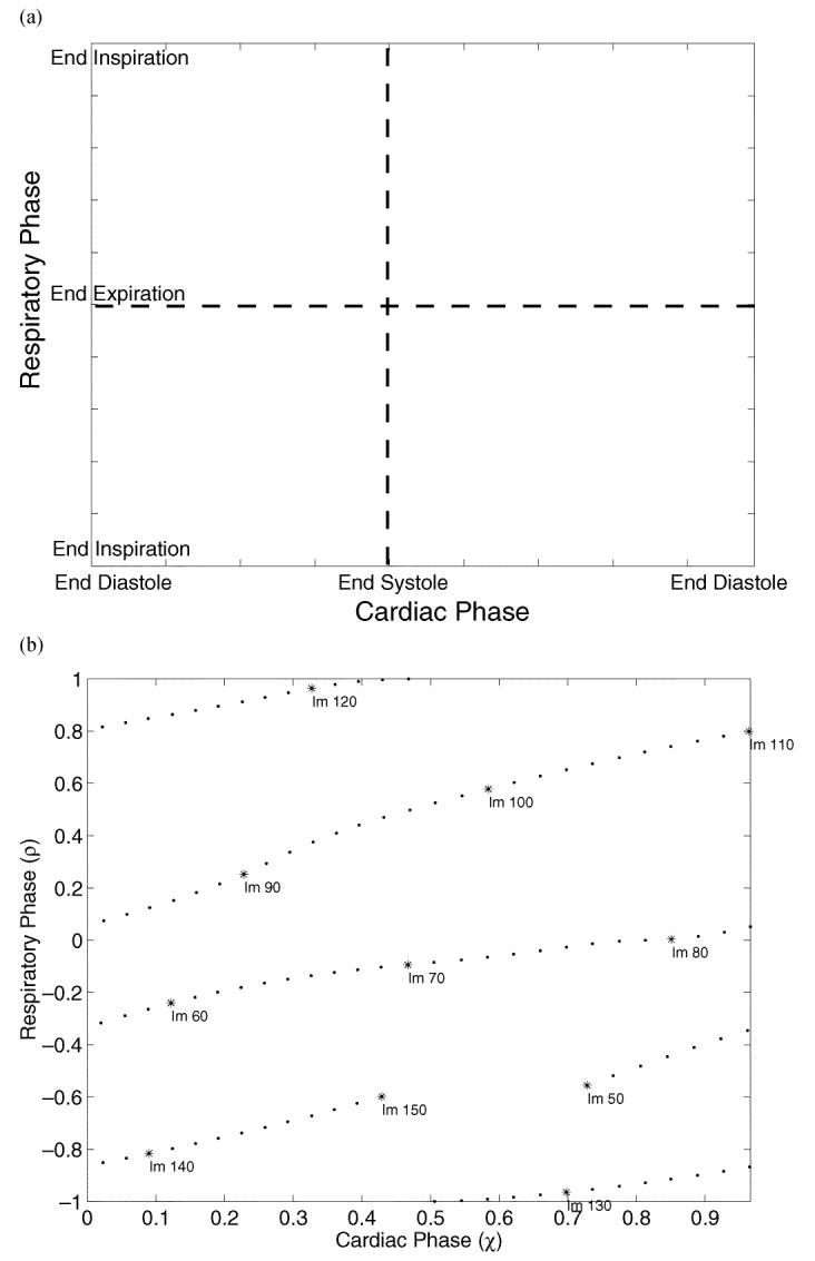
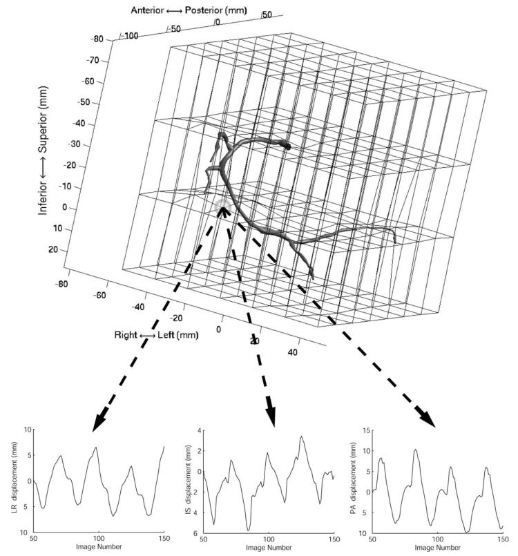
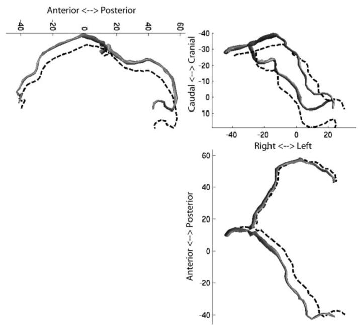
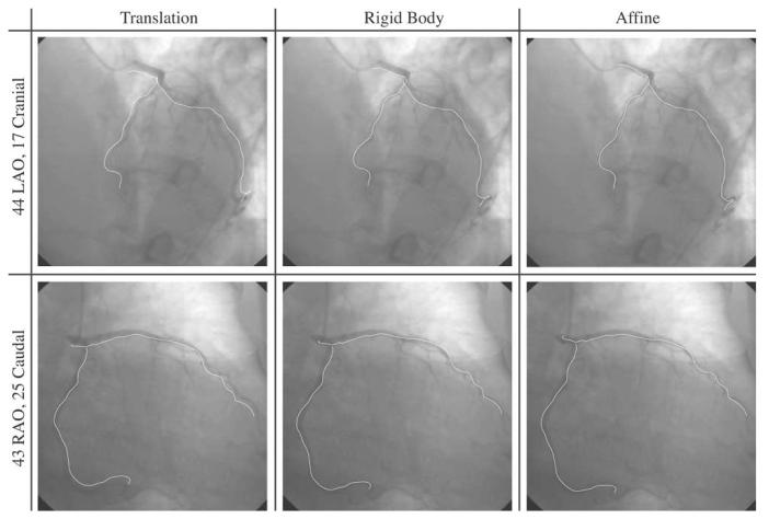
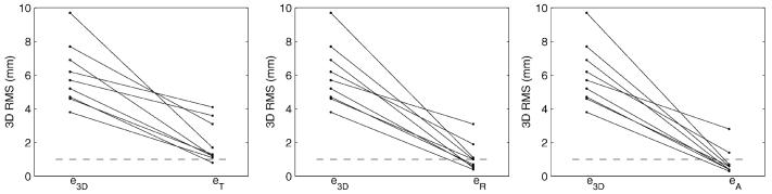
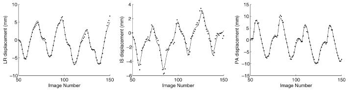
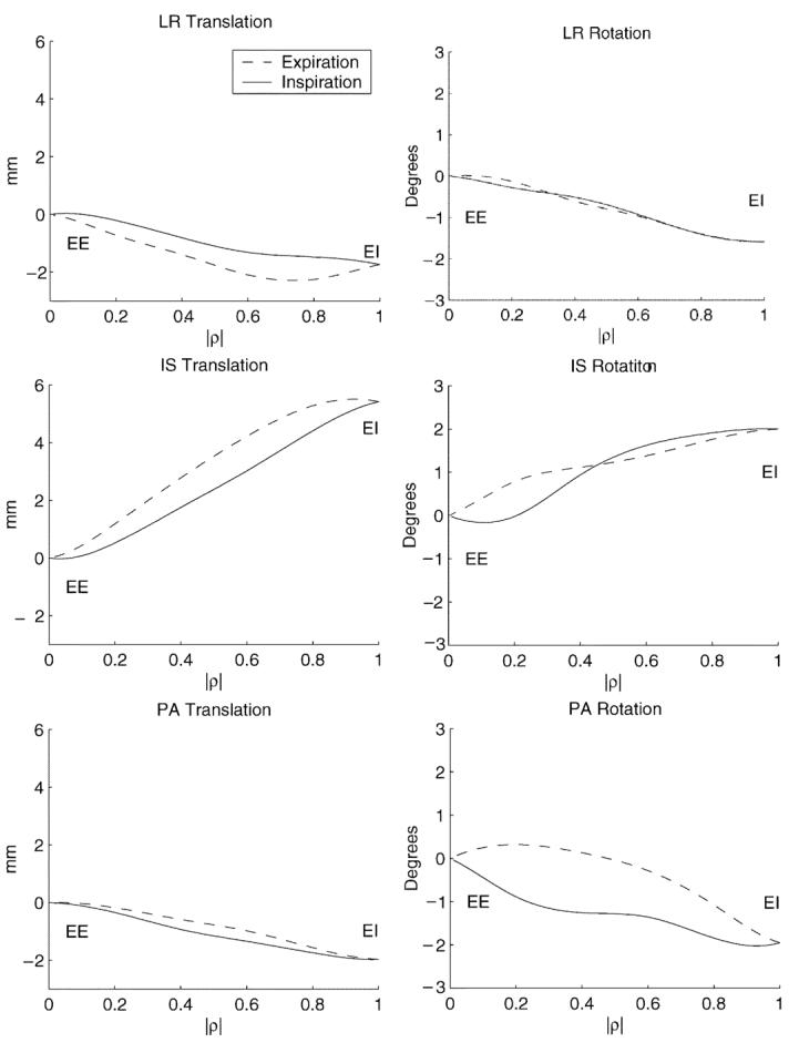
Respiratory motion compensation for cardiac imaging requires knowledge of the heart's motion and deformation during breathing. This paper presents a method for measuring the natural tidal respiratory motion of the heart from free breathing coronary angiograms. A three-dimensional (3-D) deformation field describing the cardiac and respiratory motion of the coronary arteries is recovered from a biplane acquisition. A cardiac respiratory parametric model is formulated and used to decompose the deformation field into cardiac and respiratory components. Angiograms from ten patients were analyzed. A 3-D translation motion model was sufficient for describing the motion of the heart in only two patients. For all patients, the heart translated caudally (mean, 4.9+/-1.9 mm; range, 2.4 to 8.0 mm) and underwent a cranio-dorsal rotation (mean, 1.5 degrees+/-0.9 degrees; range, 0.2 degrees to 3.5 degrees) during inspiration. In eight patients, the heart also translated anteriorly (mean, 1.3+/-1.8 mm; range, -0.4 to 5.1 mm) and rotated in a caudo-dextral direction (mean, 1.2 degrees+/-1.3 degrees; range, -1.9 degrees to 3.2 degrees).
Figures


Similar articles
-
Displacement and velocity of the coronary arteries: cardiac and respiratory motion.IEEE Trans Med Imaging. 2006 Mar;25(3):369-75. doi: 10.1109/TMI.2005.862752. IEEE Trans Med Imaging. 2006. PMID: 16524092 Free PMC article. Clinical Trial.
-
Prospective motion correction of X-ray images for coronary interventions.IEEE Trans Med Imaging. 2005 Apr;24(4):441-50. doi: 10.1109/tmi.2004.839679. IEEE Trans Med Imaging. 2005. PMID: 15822802 Clinical Trial.
-
Correction of motion artifacts in cone-beam CT using a patient-specific respiratory motion model.Med Phys. 2010 Jun;37(6):2901-9. doi: 10.1118/1.3397460. Med Phys. 2010. PMID: 20632601 Free PMC article.
-
Angle-independent measure of motion for image-based gating in 3D coronary angiography.Med Phys. 2006 May;33(5):1311-20. doi: 10.1118/1.2191133. Med Phys. 2006. PMID: 16752566
-
Image-based respiratory motion compensation for fluoroscopic coronary roadmapping.Med Image Comput Comput Assist Interv. 2010;13(Pt 3):287-94. doi: 10.1007/978-3-642-15711-0_36. Med Image Comput Comput Assist Interv. 2010. PMID: 20879411
Cited by
-
Nonrigid Motion Correction With 3D Image-Based Navigators for Coronary MR Angiography.Magn Reson Med. 2017 May;77(5):1884-1893. doi: 10.1002/mrm.26273. Epub 2016 May 13. Magn Reson Med. 2017. PMID: 27174673 Free PMC article.
-
Displacement and velocity of the coronary arteries: cardiac and respiratory motion.IEEE Trans Med Imaging. 2006 Mar;25(3):369-75. doi: 10.1109/TMI.2005.862752. IEEE Trans Med Imaging. 2006. PMID: 16524092 Free PMC article. Clinical Trial.
-
Advanced respiratory motion compensation for coronary MR angiography.Sensors (Basel). 2013 May 24;13(6):6882-99. doi: 10.3390/s130606882. Sensors (Basel). 2013. PMID: 23708271 Free PMC article. Review.
-
High-resolution, respiratory-resolved coronary MRA using a Phyllotaxis-reordered variable-density 3D cones trajectory.Magn Reson Imaging. 2023 May;98:140-148. doi: 10.1016/j.mri.2023.01.008. Epub 2023 Jan 14. Magn Reson Imaging. 2023. PMID: 36646397 Free PMC article.
-
Feasibility of volumetric-modulated arc therapy gating for cardiac radioablation using real-time ECG signal acquisition and a dynamic phantom.Med Phys. 2025 Mar;52(3):1758-1768. doi: 10.1002/mp.17582. Epub 2024 Dec 19. Med Phys. 2025. PMID: 39699040 Free PMC article.
References
-
- Axel L, Summers R, Kressel H, Charles C. Respiratory effects in two-dimensional Fourier transform MR imaging. Radiology. 1986;160:795–801. - PubMed
-
- Holland A, Goldfarb J, Edelman R. Diaphragmatic and cardiac motion during suspended breathing: Preliminary experience and implications for breath-hold MR imaging. Radiology. 1998 Nov.209(2):483–489. - PubMed
-
- Dougherty J. The relation of respiratory changes in the horizontal QRS and T-wave axes to movement of the thoracic electrodes. J. Electrocardiol. 1970;3(1):77–86. - PubMed
-
- Dougherty J. Change in the frontal QRS axis with changes in the anatomic positions of the heart. J. Electrocardiol. 1970;3(3–4):299–308. - PubMed
-
- Bogren H, Lantz B, Miller R, Mason D. Effect of respiration on cardiac motion determined by cineangiography. Acta Radiologica Diagnosis. 1977 Nov.18:609–620. - PubMed
Publication types
MeSH terms
Grants and funding
LinkOut - more resources
Full Text Sources
Other Literature Sources
