. 2004 Sep;87(3):1972-80.
doi: 10.1529/biophysj.103.037697.

All-optical constant-force laser tweezers

Affiliations

All-optical constant-force laser tweezers

Rajalakshmi Nambiar et al. Biophys J. 2004 Sep.

Abstract

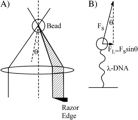
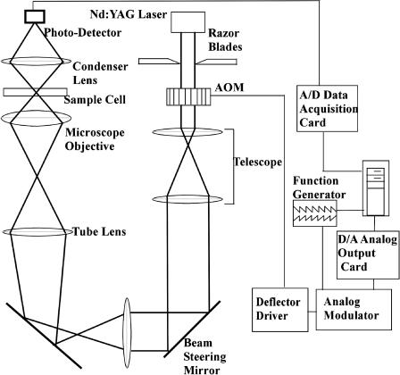
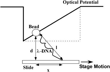
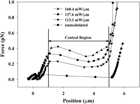
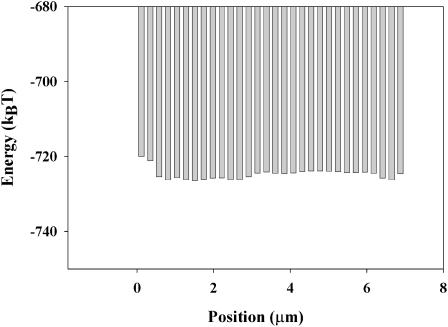
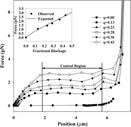
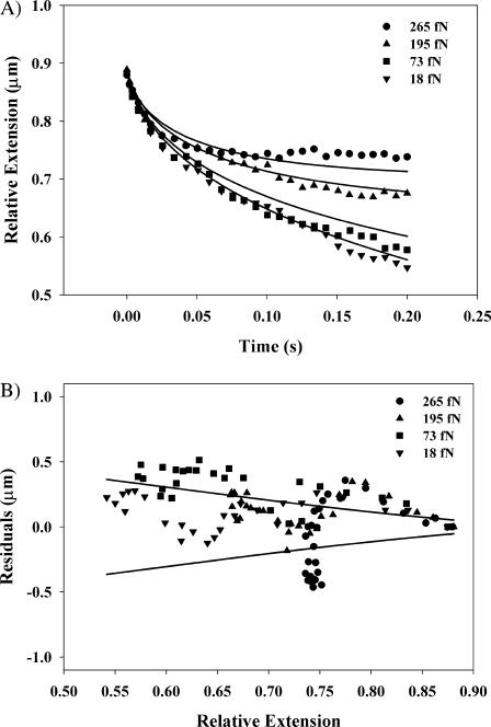
Optical tweezers are a powerful tool for the study of single biomolecules. Many applications require that a molecule be held under constant tension while its extension is measured. We present two schemes based on scanning-line optical tweezers to accomplish this, providing all-optical alternatives to force-clamp traps that rely on electronic feedback to maintain constant-force conditions for the molecule. In these schemes, a laser beam is rapidly scanned along a line in the focal plane of the microscope objective, effectively creating an extended one-dimensional optical potential over distances of up to 8 microm. A position-independent lateral force acting on a trapped particle is created by either modulating the laser beam intensity during the scan or by using an asymmetric beam profile in the back focal plane of the microscope objective. With these techniques, forces of up to 2.69 pN have been applied over distances of up to 3.4 microm with residual spring constants of <26.6 fN/microm. We used these techniques in conjunction with a fast position measurement scheme to study the relaxation of lambda-DNA molecules against a constant external force with submillisecond time resolution. We compare the results to predictions from the wormlike chain model.


Figures

FIGURE 1
FIGURE 1
(A) Ray optics model of the asymmetric beam scanning-line optical tweezers. The partial blockage of the beam in the back focal plane of the microscope objective results in a small angle Θ between the incident laser beam and normal incidence on the focal plane. The radiation pressure stemming from the back reflection from the microsphere acquires a lateral component Fs sin Θ. This force pushes the particle to the side where the beam is blocked. (B) A schematic depiction of the pull exerted by the scattering force onto a microsphere that is tethered to the microscope coverglass by a λ-DNA molecule.
FIGURE 2
FIGURE 2
Schematic diagram of the scanning-line optical tweezer setup. The laser beam is deflected by a computer-controlled acousto-optic modulator (AOM) and imaged by a telescope system onto the back focal plane of a microscope objective. The beam profile in this plane can be controlled by a pair of knife edges in a conjugate plane. The laser beam is focused into the sample cell by a high-numerical-aperture microscope objective. A condenser lens images the transmitted laser light onto a fast photo diode. A fast data-acquisition system measures the transmitted light intensity synchronously with the beam deflection.
FIGURE 3
FIGURE 3
Intensity of the transmitted laser light as a function time and position during the scan. The pronounced dip occurs when the scanning laser beam hits the trapped microsphere. The position of the microsphere in the potential is determined from the timing of the minimum with respect to the scan.
FIGURE 4
FIGURE 4
Sketch of a microsphere tethered to a glass coverslip by a λ-DNA molecule, in an optical ramp-type potential. The slide is mounted on a piezo-actuated microscope stage that is moved against the optical force acting on the particle. The extension of the DNA molecule is used to determine the magnitude of the optical force, taking the geometry above into account.
FIGURE 5
FIGURE 5
Optical forces acting on a microsphere in an amplitude-modulated scanning-line laser trap. The forces associated with different modulation depth are determined from the extension of a λ-DNA molecule that tethers the microsphere to the coverglass. The central 4-μm-wide region of the optical potential exhibits relatively constant forces, whose averages are calculated for this region and tabulated in Table 1. Outside this central region, the edges of the optical potential become visible as either disappearing or strongly increasing forces.
FIGURE 6
FIGURE 6
Potential energy of a microsphere in an unmodulated scanning-line trap. Potential differences within the trap were determined from the probability distribution of the position of a diffusing bead. The offset is estimated from the stiffness of an equivalent stationary trap.
FIGURE 7
FIGURE 7
Optical force as a function of position in the potential generated by asymmetries in the beam profile. Blocking a larger fraction q of the beam leads to an increased asymmetry of the beam and yields a higher optical force acting on the trapped microsphere. The graph shows the force profile obtained for a single tethered bead. The force is relative constant over a central 4-μm-wide region, for which the average force is computed. The inset shows a comparison between the average forces measured and the theoretical prediction for the lateral component of the optical scattering force, Eq. 4.
FIGURE 8
FIGURE 8
Relaxation of an extended λ-DNA molecule against an external force. (A) Relative extension of the DNA molecule as a function of time against different applied lateral optical forces. Data were taken at a rate of 20 kHz and approximately every hundredth data point is shown for clarity. The solid lines represent the theoretical predictions from the wormlike chain model as modified for our experimental geometry. The optical forces are determined by mapping the optical ramp potential, and then averaged over the portion of the trap through which the microsphere moves while the DNA relaxes. (B) Shows the differences between the theoretical and actual extensions of the DNA molecule, as plotted in A. The solid lines indicate the expected thermal noise that is predicted by the equipartition theorem.

References

    1. Berg-Sørensen, K., L. Oddershede, E. L. Florin, and H. Flyvbjerg. 2003. Unintended filtering in a typical photodiode system for optical tweezers. J. Appl. Phys. 93:3167–3176.
    1. Crocker, J. C., J. A. Matteo, A. D. Dinsmore, and A. G. Yodh. 1998. Entropic attraction and repulsion in binary colloids probed with a line optical tweezer. Phys. Rev. Lett. 82:4352–4355.
    1. Faucheux, L. P., L. S. Bordieu, P. D. Kaplan, and A. J. Libchaber. 1995a. Optical thermal ratchet. Phys. Rev. Lett. 74:1504–1507. - PubMed
    1. Faucheux, L. P., Stolovitzky, G., and A. J. Libchaber. 1995b. Periodic forcing of a Brownian particle. Phys. Rev. E. 51:5239–5250. - PubMed
    1. Finer, J. T., R. M. Simmons, and J. A. Spudich. 1994. Single myosin molecule mechanics: piconewton forces and nanometre steps. Nature (Lond.). 368:113–119. - PubMed

Publication types

LinkOut - more resources