Review
. 2004 Sep;205(3):159-77.
doi: 10.1111/j.0021-8782.2004.00330.x.

Cardiac anatomy revisited

Affiliations
Review

Cardiac anatomy revisited

Robert H Anderson et al. J Anat. 2004 Sep.

Abstract

In tomorrow's world of clinical medicine, students will increasingly be confronted by anatomic displays reconstructed from tomographically derived images. These images all display the structure of the various organs in anatomical orientation, this being determined in time-honoured fashion by describing the individual in the 'anatomical position', standing upright and facing the observer. It follows from this approach that all adjectives used to describe the organs should be related to the three orthogonal planes of the body. Unfortunately, at present this convention is not followed for the heart, even though most students are taught that the so-called 'right chambers' are, in reality, in front of their 'left' counterparts. Rigorous analysis of the tomographic images already available, along with comparison with dissected hearts displayed in attitudinally correct orientation, calls into question this continuing tendency to describe the heart in terms of its own orthogonal axes, but with the organ positioned on its apex, so that the chambers can artefactually be visualized with the right atrium and right ventricle in right-sided position. Although adequate for describing functional aspects, such as 'right-to-left' shunting across intracardiac communications, this convention falls short when used to describe the position of the artery that supplies the diaphragmatic surface of the heart. Currently known as the 'posterior descending artery', in reality it is positioned inferiorly, and its blockage produces inferior myocardial infarction. In this review, we extend the concept of describing cardiac structure in attitudinally correct orientation, showing also how access to tomographic images clarifies many aspects of cardiac structure previously considered mysterious and arcane. We use images prepared using new techniques such as magnetic resonance imaging and computerized tomography, and compare them with dissection of the heart made in time-honoured fashion, along with cartoons to illustrate contentious topics. We argue that there is much to gain by describing the components of the heart as seen in the anatomical position, along with all other organs and structures in the body. We recognize, nonetheless, that such changes will take many years to be put into practice, if at all.


Figures
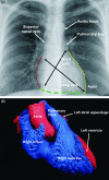
Fig. 1
Fig. 1
The frontal chest radiograph (a) shows the outline of the cardiac silhouette relative to the thorax. Note that the axes of the heart itself are well out of skew relative to the axes of the body. The right border of the heart is shown by the red dotted line, the left border, or obtuse border of the ventricular mass, by the yellow dotted line, and the diaphragmatic border, or acute border of the ventricular mass, by the green dashed line. A cast of the normal heart (b), photographed in attitudinally appropriate position, with the so-called ‘right heart’ cast in blue, and the ‘left heart’ cast in red, shows the chambers corresponding to the silhouette. See also Fig. 2.
Fig. 2
Fig. 2
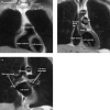
The cuts through the heart in the coronal plane, running from the front (a) to the back (c), show the different chambers that contribute to the borders of the cardiac silhouette as seen in the frontal chest radiograph (Fig. 1). See text for further discussion.
Fig. 3
Fig. 3
The outlines of the cardiac valvar leaflets from the data set shown in Fig. 2 have been reconstructed in the frontal plane (a) and superimposed on the chest radiograph (b).
Fig. 4
Fig. 4
The outlines of the cardiac valves reconstructed from the magnetic resonance images are shown in lateral projection, and compared with the short axis of the heart as seen in left anterior oblique projection looking upwards from the cardiac apex. The green dotted line shows the fibrous continuity between the leaflets of the aortic and mitral valves that forms the roof of the left ventricle. Note that, in comparison, the roof of the right ventricle is muscular, the supraventricular crest (red arrow) being interposed between the leaflets of the tricuspid and pulmonary valves.
Fig. 5
Fig. 5
The short axis of the heart is photographed from above and behind having removed the atrial chambers and the arterial trunks. Note the obliquity of the relationship between the aortic and pulmonary valves, and that the pulmonary trunk is lifted away from the ventricular base by the subpulmonary muscular infundibulum. See also Fig. 4.
Fig. 6
Fig. 6
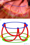
The upper panel shows the opened pulmonary root having removed the leaflets of the pulmonary valve. The semilunar attachments of the leaflets are marked by the red line, with the blue line showing the sinutubular junction, the yellow line the anatomic junction between the muscular infundibulum and the arterial wall of the pulmonary trunk, and the green line the ring made by joining together the basal attachments of the three arterial valvar leaflets. The lower panel shows the three-dimensional crown-like configuration produced by interdigitation of the semilunar attachments with the three rings existing in the root. There is no ‘annulus’ supporting the attachments of the leaflets – see text for further discussion.
Fig. 7
Fig. 7
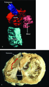
The ventricles and arterial trunks have been reconstructed from a data set obtained using magnetic resonance imaging, and the so-called right-sided structures coloured in blue, with the left-sided structures coloured in red. Note the spiralling arrangements of the arterial trunks. The apparent hole in the cast of the right ventricle is produced by the prominent right ventricular trabeculations.
Fig. 8
Fig. 8
The magnetic resonance image, taken in lateral projection (sagittal plane), shows that the so-called right-sided structures, the right ventricle, infundibulum and pulmonary trunk, are in reality anterior to their left-sided counterparts.
Fig. 9
Fig. 9
A slice parallel to the image shown in Fig. 8 reveals the location of the oesophagus directly posterior to the so-called left-sided cardiac structures.
Fig. 10
Fig. 10
The section across the ventricular mass in short axis shows that the angle between the sternocostal and diaphragmatic surfaces is acute, giving the acute margin, whereas that between the sternocostal and pulmonary margins is obtuse. It also shows how the short axis of the left ventricle can be divided into quadrants (red lines). Quadrant 4 is obviously positioned inferiorly. Currently, however, nuclear cardiologists describe the opposite quadrant (2) as being ‘anterior’. As the images show, this quadrant is really positioned superiorly. It is the septal quadrant (1) that is anterior.
Fig. 11
Fig. 11
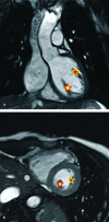
The magnetic resonance images have been programmed to permit the data set to be cut in the plane of the coronary arteries. The section shows the obtuse marginal branches of the circumflex artery irrigating the obtuse margin of the ventricular mass, with the right coronary artery taking its acute turn at the acute margin (star).
Fig. 12
Fig. 12
The section across the ventricular mass in its own short axis shows how the postero-inferior extent of the ventricular septum (red star) cuts the atrioventricular junction between the right (RAVO) and left (LAVO) atrioventricular orifices. This corresponds to the so-called crux of the heart (see also Fig. 22). Note how the atrial myocardium (green dotted line) overlaps the ventricular myocardium at this point, the two muscle masses separated by the fibro-fatty tissue of the atrioventricular groove.
Fig. 13
Fig. 13
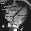
The long axis taken along the heart itself shows the so-called ‘four-chamber’ projection.
Fig. 14
Fig. 14
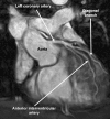
The magnetic resonance image in frontal projection shows that the so-called ‘anterior descending coronary artery’ emerges from the aorta in superior position.
Fig. 15
Fig. 15
This section of a developing human heart at Carnegie stage 15, and taken in ‘four-chamber’ projection, shows that, at early stages, the systemic venous sinus is separated from the remainder of the developing right atrium by well-formed right and left venous valves.
Fig. 16
Fig. 16
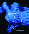
The cast of the right atrium, photographed in lateral projection from the right side, shows how the pectinated appendage interposes between the smooth-walled systemic venous sinus, receiving the superior and inferior caval veins (SCV, ICV) and the coronary sinus, and the vestibule of the tricuspid valve.
Fig. 17
Fig. 17
The cast of the left atrium shows that the pectinate muscles are confined within the tubular appendage, but an extensive smooth-walled body interposes between the vestibule of the mitral valve and the pulmonary venous component.
Fig. 18
Fig. 18
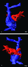
Reconstruction from magnetic resonance images showing the interrelations of the systemic and pulmonary venous components from (a) the front and (b) the back.
Fig. 19
Fig. 19
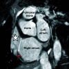
This cut in the short axis of the heart itself shows the triangular right atrial appendage (white star), with a broad junction to the atrium (double-headed arrow), marked by the prominent terminal crest (red star). In comparison, the junction of the left atrial appendage with the atrium is narrow, and is not marked by any terminal crest.
Fig. 20
Fig. 20
The cast of the cardiac chambers, photographed to show the diaphragmatic aspect, shows how the coronary sinus occupies the left atrioventricular groove, receiving the great cardiac vein at its origin at the site of the oblique vein of the left atrium, and the middle cardiac vein at the crux.
Fig. 21
Fig. 21
The heart has been sectioned in its own long axis to reveal the four cardiac chambers (compare with Fig. 13). Note the coarse trabeculations at the apex of the right ventricle in comparison with the smooth surface of the left ventricle.
Fig. 22
Fig. 22
The mitral valve is photographed from above to show its atrial aspect in closed position. The two leaflets close along a solitary zone of apposition, with multiple slits in the larger leaflet ensuring competent coaptation. Original photograph reproduced by kind permission of Dr Val S. Galstyan, Armenia.
Fig. 23
Fig. 23
The magnetic resonance images in frontal (a) and short axis (b) planes across the body show that the paired papillary muscles supporting the mitral valves are positioned adjacent to the septum and inferiorly (yellow star with red line), and posteriorly and superiorly (red star with yellow line).
Fig. 24
Fig. 24
The two leaflets of the mitral valve, both supported all along their free edge by tendinous cords, guard markedly dissimilar lengths of the valvar orifice, the mural leaflet (red) being long and shallow whereas the aortic leaflet (blue) is short and deep.
Fig. 25
Fig. 25
The photograph of the septal aspect of the right ventricle shows the arrangement of the muscle bundles, with the supraventricular crest inserting between the limbs of the septomarginal trabeculation. The septomarginal trabeculation has a body (blue star) and superior (red star) and inferior (yellow star) limbs, the two limbs clasping the insertion of the supraventricular crest (yellow dotted line). The medial papillary muscle arises from the inferior limb. Note also the septoparietal trabeculations and the moderator band.
Fig. 26
Fig. 26
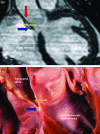
The magnetic resonance image (upper) and anatomic section (lower) show the relationships produced because of attachment of the leaflets of the aortic valve at the sinutubular junction. Because of the height of this attachment (red arrows), a fibrous extension of the aortic root separates the outflow tract from the transverse sinus of the periciardium (yellow double-headed arrow). The blue arrow shows the attachment of the wall of the right atrium.
Fig. 27
Fig. 27
The long axis (oblique axial) image across the atrial chambers shows the structure of the atrial septum. Note that the septum itself is directly related to the aorta. The yellow double-headed arrow is through the floor of the oval fossa. The supero-posterior rim of the fossa, however, often described as the ‘septum secundum’, is shown by the image to be a deep infolding between the connections of the pulmonary veins to the left atrium and the caval veins to the right atrium. This area is better described as the interatrial groove (green and red arrow).
Fig. 28
Fig. 28
The section through the aortic root shows the relationships of the membranous part of the septum. The hingepoint of the tricuspid valve, emphasized by the blue dotted line, divided the fibrous part of the septum into atrioventricular (red arrow) and interventricular (yellow arrow) components.
Fig. 29
Fig. 29
This frontal section, through the part of the muscular septum that supports the membranous septum (yellow arrow) and the aortic root, shows that the muscular septum itself, by virtue of the deeply ‘wedged’ location of the left ventricular outflow tract, separates the inlet of the right ventricle from the subaortic outlet of the left ventricle (green and red arrow). Previously, we had considered this part of the septum to be an ‘inlet septum’. In reality, it is an ‘inlet–outlet’ septum.
Fig. 30
Fig. 30
Computed tomography section through the right coronary artery shows the potential for the new imaging techniques. The image, expanded in the inset, has revealed the presence of a calcified, atherosclerotic plaque (white arrows, black arrow shows calcification), significantly reducing the calibre of the vessels, and potentially producing myocardial ischaemia. Reproduced by kind permission of Dr Ronald Kuzo, MD (Mayo Clinic, Jacksonville, FL, USA), and Professor Jan Bogaert, MD, PhD (Gasthuisberg University Hospital, Leuven, Belgium).

References

    1. American Heart Association Writing Group on Myocardial Segmentation and Registration for Cardiac Imaging. Standardized myocardial segmentation and nomenclature for tomographic imaging of the heart. Circulation. 2002;105:539–547. - PubMed
    1. Anderson RH, Brown NA. The anatomy of the heart revisited. Anat. Rec. 1996;246:1–7. - PubMed
    1. Anderson RH, Ho SY. What is a ventricle? Ann. Thorac. Surg. 1998;66:616–620. - PubMed
    1. Anderson RH, Webb S, Brown NA. Defective lateralisation in children with congenitally malformed hearts. Cardiol. Young. 1998;8:512–531. - PubMed
    1. Anderson RH, Webb S, Brown NA. Clinical anatomy of the atrial septum with reference to its developmental components. Clin. Anat. 1999;12:362–374. - PubMed

Publication types