

The mechanics of surface expansion anisotropy in Medicago truncatula root hairs
- PMID: 15448192
- PMCID: PMC523385
- DOI: 10.1104/pp.104.043752
The mechanics of surface expansion anisotropy in Medicago truncatula root hairs
Abstract
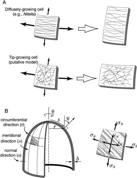
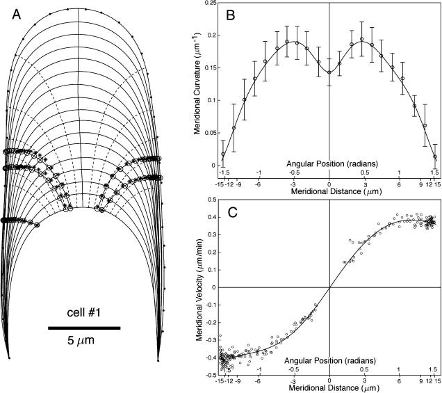
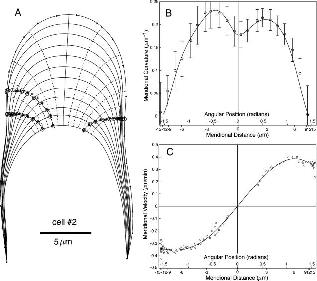
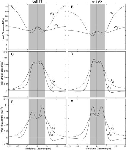
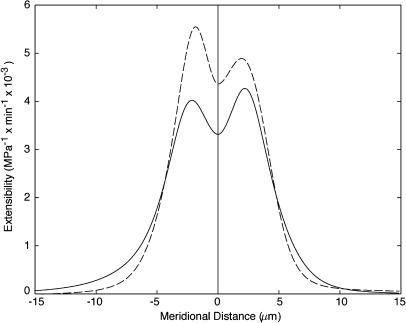
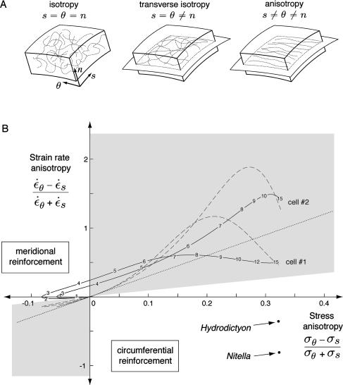
Wall expansion in tip-growing cells shows variations according to position and direction. In Medicago truncatula root hairs, wall expansion exhibits a strong meridional gradient with a maximum near the pole of the cell. Root hair cells also show a striking expansion anisotropy, i.e. over most of the dome surface the rate of circumferential wall expansion exceeds the rate of meridional expansion. Concomitant measurements of expansion rates and wall stresses reveal that the extensibility of the cell wall must vary abruptly along the meridian of the cell to maintain the gradient of wall expansion. To determine the mechanical basis of expansion anisotropy, we compared measurements of wall expansion with expansion patterns predicted from wall structural models that were either fully isotropic, transversely isotropic, or fully anisotropic. Our results indicate that a model based on a transversely isotropic wall structure can provide a good fit of the data although a fully anisotropic model offers the best fit overall. We discuss how such mechanical properties could be controlled at the microstructural level.
Figures
Similar articles
-
Cell surface expansion in polarly growing root hairs of Medicago truncatula.Plant Physiol. 2000 Nov;124(3):959-70. doi: 10.1104/pp.124.3.959. Plant Physiol. 2000. PMID: 11080274 Free PMC article.
-
Identification of legume RopGEF gene families and characterization of a Medicago truncatula RopGEF mediating polar growth of root hairs.Plant J. 2011 Jan;65(2):230-43. doi: 10.1111/j.1365-313X.2010.04414.x. Plant J. 2011. PMID: 21223388
-
Texture of cellulose microfibrils of root hair cell walls of Arabidopsis thaliana, Medicago truncatula, and Vicia sativa.J Microsc. 2012 Jul;247(1):60-7. doi: 10.1111/j.1365-2818.2012.03611.x. Epub 2012 Mar 28. J Microsc. 2012. PMID: 22458271
-
An anisotropic-viscoplastic model of plant cell morphogenesis by tip growth.Int J Dev Biol. 2006;50(2-3):209-22. doi: 10.1387/ijdb.052066jd. Int J Dev Biol. 2006. PMID: 16479489 Review.
-
Anisotropic expansion of the plant cell wall.Annu Rev Cell Dev Biol. 2005;21:203-22. doi: 10.1146/annurev.cellbio.20.082503.103053. Annu Rev Cell Dev Biol. 2005. PMID: 16212493 Review.
Cited by
-
How to shape a cylinder: pollen tube as a model system for the generation of complex cellular geometry.Sex Plant Reprod. 2010 Mar;23(1):63-71. doi: 10.1007/s00497-009-0121-4. Epub 2009 Nov 18. Sex Plant Reprod. 2010. PMID: 20165964 Review.
-
Computational morphodynamics: a modeling framework to understand plant growth.Annu Rev Plant Biol. 2010;61:65-87. doi: 10.1146/annurev-arplant-042809-112213. Annu Rev Plant Biol. 2010. PMID: 20192756 Free PMC article. Review.
-
Mercury-sensitive water channels as possible sensors of water potentials in pollen.J Exp Bot. 2013 Nov;64(16):5195-205. doi: 10.1093/jxb/ert311. Epub 2013 Oct 5. J Exp Bot. 2013. PMID: 24098048 Free PMC article.
-
Finite element model of polar growth in pollen tubes.Plant Cell. 2010 Aug;22(8):2579-93. doi: 10.1105/tpc.110.075754. Epub 2010 Aug 10. Plant Cell. 2010. PMID: 20699395 Free PMC article.
-
Microfilament orientation constrains vesicle flow and spatial distribution in growing pollen tubes.Biophys J. 2009 Oct 7;97(7):1822-31. doi: 10.1016/j.bpj.2009.07.038. Biophys J. 2009. PMID: 19804712 Free PMC article.
References
-
- Belford DS, Preston RD (1961) The structure and growth of root hairs. J Exp Bot 12: 157–168
-
- Bibikova TN, Blancaflor EB, Gilroy S (1999) Microtubules regulate tip growth and orientation in root hairs of Arabidopsis thaliana. Plant J 17: 657–665 - PubMed
-
- Chaplain MAJ, Sleeman BD (1990) An application of membrane theory to tip morphogenesis in Acetabularia. J Theor Biol 146: 177–200 - PubMed
-
- Chen JCW (1973) The kinetics of tip growth in the Nitella rhizoid. Plant Cell Physiol 14: 631–640
Publication types
MeSH terms
LinkOut - more resources
Full Text Sources
