Multiarm spirals in a two-dimensional cardiac substrate
- PMID: 15492227
- PMCID: PMC524429
- DOI: 10.1073/pnas.0400984101
Multiarm spirals in a two-dimensional cardiac substrate
Abstract
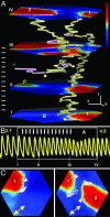
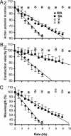
A variety of chemical and biological nonlinear excitable media, including heart tissue, can support stable, self-organized waves of activity in a form of rotating single-arm spirals. In particular, heart tissue can support stationary and meandering spirals of electrical excitation, which have been shown to underlie different forms of cardiac arrhythmias. In contrast to single-arm spirals, stable multiarm spirals (multiple spiral waves that rotate in the same direction around a common organizing center) have not been demonstrated and studied yet in living excitable tissues. Here, we show that persistent multiarm spirals of electrical activity can be induced in monolayer cultures of neonatal rat heart cells by a short, rapid train of electrical point stimuli applied during single-arm-spiral activity. Stable formation is accomplished only in monolayers that show a relatively broad and steep dependence of impulse wavelength and propagation velocity on rate of excitation. The resulting multiarm spirals emit waves of electrical activity at rates faster than for single-arm spirals and exhibit two distinct behaviors, namely "arm-switching" and "tip-switching." The phenomenon of rate acceleration due to an increase in the number of spiral arms possibly may underlie the acceleration of functional reentrant tachycardias paced by a clinician or an antitachycardia device.
Figures


Similar articles
-
Collision-based spiral acceleration in cardiac media: roles of wavefront curvature and excitable gap.Biophys J. 2010 Apr 7;98(7):1119-28. doi: 10.1016/j.bpj.2009.12.4281. Biophys J. 2010. PMID: 20371311 Free PMC article.
-
Spiral waves of excitation underlie reentrant activity in isolated cardiac muscle.Circ Res. 1993 Mar;72(3):631-50. doi: 10.1161/01.res.72.3.631. Circ Res. 1993. PMID: 8431989
-
Stationary and drifting spiral waves of excitation in isolated cardiac muscle.Nature. 1992 Jan 23;355(6358):349-51. doi: 10.1038/355349a0. Nature. 1992. PMID: 1731248
-
Optical imaging of arrhythmias in tissue culture.J Electrocardiol. 2006 Oct;39(4 Suppl):S2-6. doi: 10.1016/j.jelectrocard.2006.04.010. J Electrocardiol. 2006. PMID: 17015066 Review.
-
Controlling excitable wave behaviors through the tuning of three parameters.Biol Cybern. 2019 Apr;113(1-2):61-70. doi: 10.1007/s00422-018-0771-0. Epub 2018 Jul 28. Biol Cybern. 2019. PMID: 30056608 Review.
Cited by
-
Engineered bacterial voltage-gated sodium channel platform for cardiac gene therapy.Nat Commun. 2022 Feb 2;13(1):620. doi: 10.1038/s41467-022-28251-6. Nat Commun. 2022. PMID: 35110560 Free PMC article.
-
Characterizing functional stem cell-cardiomyocyte interactions.Regen Med. 2010 Jan;5(1):87-105. doi: 10.2217/rme.09.69. Regen Med. 2010. PMID: 20017697 Free PMC article. Review.
-
Pluripotent stem cell-derived cardiac tissue patch with advanced structure and function.Biomaterials. 2011 Dec;32(35):9180-7. doi: 10.1016/j.biomaterials.2011.08.050. Epub 2011 Sep 8. Biomaterials. 2011. PMID: 21906802 Free PMC article.
-
Rotors and the dynamics of cardiac fibrillation.Circ Res. 2013 Mar 1;112(5):849-62. doi: 10.1161/CIRCRESAHA.111.300158. Circ Res. 2013. PMID: 23449547 Free PMC article. Review.
-
Multistable spatiotemporal patterns of cardiac activity.Proc Natl Acad Sci U S A. 2005 Jul 26;102(30):10409-10. doi: 10.1073/pnas.0504511102. Epub 2005 Jul 18. Proc Natl Acad Sci U S A. 2005. PMID: 16027355 Free PMC article. No abstract available.
References
-
- Winfree, A. (1972) Science 175, 634-636. - PubMed
-
- Agladze, K. I. & Krinsky, V. I. (1982) Nature 296, 424-426.
-
- Vanag, V. K. & Epstein, I. R. (2001) Science 294, 835-837. - PubMed
-
- Ertl, G. (1991) Science 254, 1750-1755. - PubMed
-
- Lechleiter, J., Girard, S., Peralta, E. & Clapham, D. (1991) Science 252, 123-126. - PubMed
Publication types
MeSH terms
Grants and funding
LinkOut - more resources
Full Text Sources
Other Literature Sources

