. 2004 Dec 6;200(11):1445-54.
doi: 10.1084/jem.20040217. Epub 2004 Nov 22.

Structural basis for the restoration of TCR recognition of an MHC allelic variant by peptide secondary anchor substitution

Affiliations

Structural basis for the restoration of TCR recognition of an MHC allelic variant by peptide secondary anchor substitution

Michael J Miley et al. J Exp Med. .

Abstract

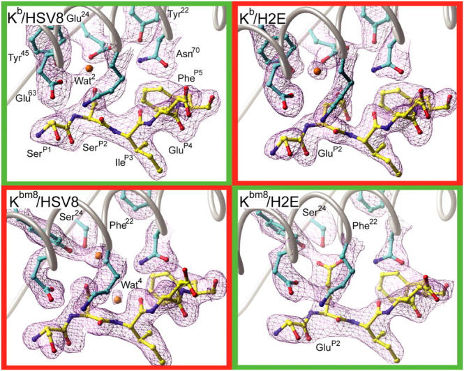
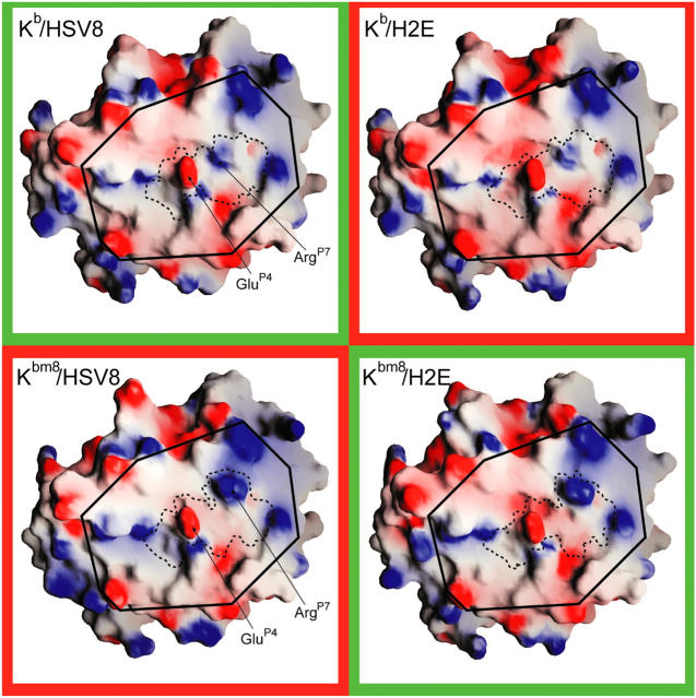
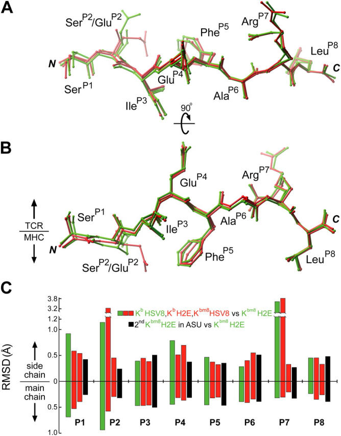
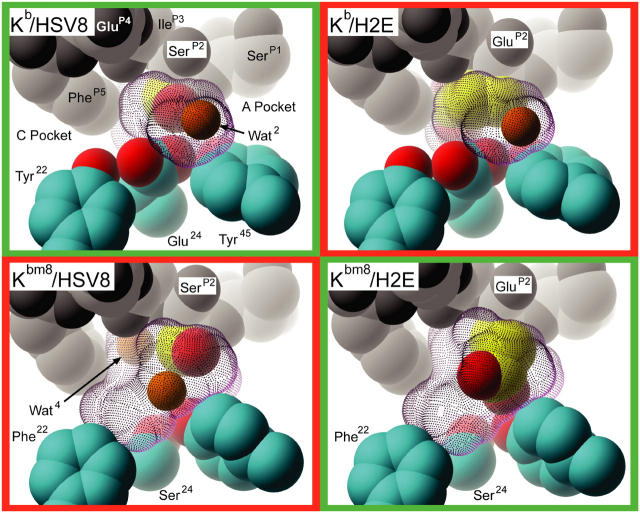
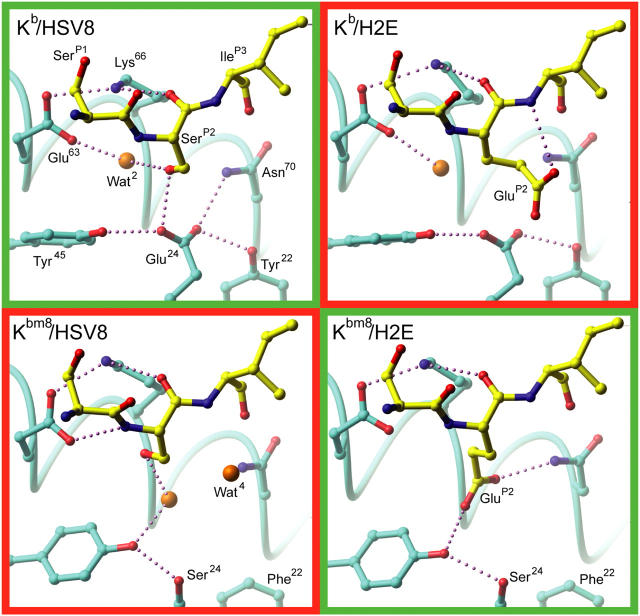
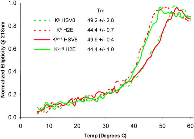
Major histocompatibility complex (MHC) class I variants H-2K(b) and H-2K(bm8) differ primarily in the B pocket of the peptide-binding groove, which serves to sequester the P2 secondary anchor residue. This polymorphism determines resistance to lethal herpes simplex virus (HSV-1) infection by modulating T cell responses to the immunodominant glycoprotein B(498-505) epitope, HSV8. We studied the molecular basis of these effects and confirmed that T cell receptors raised against K(b)-HSV8 cannot recognize H-2K(bm8)-HSV8. However, substitution of Ser(P2) to Glu(P2) (peptide H2E) reversed T cell receptor (TCR) recognition; H-2K(bm8)-H2E was recognized whereas H-2K(b)-H2E was not. Insight into the structural basis of this discrimination was obtained by determining the crystal structures of all four MHC class I molecules in complex with bound peptide (pMHCs). Surprisingly, we find no concerted pMHC surface differences that can explain the differential TCR recognition. However, a correlation is apparent between the recognition data and the underlying peptide-binding groove chemistry of the B pocket, revealing that secondary anchor residues can profoundly affect TCR engagement through mechanisms distinct from the alteration of the resting state conformation of the pMHC surface.


Figures

Figure 1.
Figure 1.
Crystallographic electron density maps of the pMHC B pockets. Sigma-weighted simulated annealing Fo-Fc omit electron density maps contoured at 3.5σ around the B pocket regions of all four pMHCs. (cyan) Kb and Kbm8 carbon; (yellow) HSV8 and H2E peptide carbon; (red) oxygen; (blue) nitrogen; (orange) water. Recognized pMHCs are in green boxes and unrecognized pMHCs are in red boxes.
Figure 2.
Figure 2.
pMHC electrostatic surface properties. The membrane-distal, peptide-binding platforms of all four pMHCs are depicted. Electrostatic properties were mapped to the molecular surfaces using the program GRASP. Surface colors are contoured from red (−8kT) to blue (+8kT). Elements of the surface corresponding to the peptides are approximately enclosed with dashed lines. (solid lines) The portion of the pMHC surface containing modeled 2C TCR contacts is boxed.
Figure 3.
Figure 3.
Positional deviation analysis of MHC presented peptides. Peptides from all four pMHCs have been superimposed via their α1/α2 domains. They are shown from a top-down perspective (A) and a side view (B). (green) Peptides from recognized pMHCs. (red) Peptides from unrecognized pMHCs. The large difference observed for ArgP7 is due to alternate crystal packing arising from different space groups. (C) The positional differences of the peptides were quantitated and graphed to denote per residue main and side chain differences in reference to Kbm8–H2E. Recognized peptides (green) and unrecognized peptides (red) have been compared with one of the peptides from the Kbm8–H2E crystal structure (chain Q of 1RJZ), with the differences between the two peptides in the Kbm8–H2E ASU (black) representing a measure of experimental error.
Figure 4.
Figure 4.
Surface representation of pMHC B pockets. The Tyr22 to Phe22, and Glu24 to Ser24 mutations present in Kbm8 relative to Kb result in a larger, more accommodating, and neutral B pocket. Residues are represented as CPK models. Peptide atoms are in grayscale. (Yellow) P2 side chain carbon; (cyan) MHC carbon; (red) MHC oxygen; (orange) waters. The molecular surfaces of the B pockets are represented with purple dots.
Figure 5.
Figure 5.
pMHC B pocket hydrogen bonding schemes. The B pocket hydrogen bonding networks of all four pMHCs are depicted. The specific interactions of peptide P2 residues with MHC are highlighted. Recognized pMHCs are in green boxes and the unrecognized pMHCs are in red boxes. (cyan) MHC carbon atoms; (yellow) peptide carbon; (red) oxygen; (blue) nitrogen; (orange) water. Potential hydrogen bonds are depicted as small purple spheres.
Figure 6.
Figure 6.
pMHC thermostability as measured by CD. CD ellipticity data at 218 nm corresponding to the first melting transition was normalized to a scale of 0 to 1. The Tm for each pMHC is noted in the legend. All pMHCs experienced a second transition at higher temperatures with a corresponding Tm of ∼69°C, which we interpret as the unfolding of mβ2m (reference 32).

References

    1. Matsumura, M., D.H. Fremont, P.A. Peterson, and I.A. Wilson. 1992. Emerging principles for the recognition of peptide antigens by MHC class I molecules. Science. 257:927–934. - PubMed
    1. Madden, D.R. 1995. The three-dimensional structure of peptide-MHC complexes. Annu. Rev. Immunol. 13:587–622. - PubMed
    1. Bjorkman, P.J., M.A. Saper, B. Samraoui, W.S. Bennett, J.L. Strominger, and D.C. Wiley. 1987. The foreign antigen binding site and T cell recognition regions of class I histocompatibility antigens. Nature. 329:512–518. - PubMed
    1. Rammensee, H.G., K. Falk, and O. Rotzschke. 1993. Peptides naturally presented by MHC class I molecules. Annu. Rev. Immunol. 11:213–244. - PubMed
    1. van der Merwe, P.A., and S.J. Davis. 2003. Molecular interactions mediating T cell antigen recognition. Annu. Rev. Immunol. 21:659–684. - PubMed

Publication types