. 2004;129(4):915-34.
doi: 10.1016/j.neuroscience.2004.06.076.

Freeze-fracture and immunogold analysis of aquaporin-4 (AQP4) square arrays, with models of AQP4 lattice assembly

Affiliations

Freeze-fracture and immunogold analysis of aquaporin-4 (AQP4) square arrays, with models of AQP4 lattice assembly

J E Rash et al. Neuroscience. 2004.

Abstract

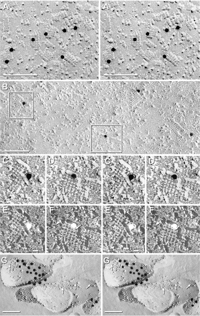
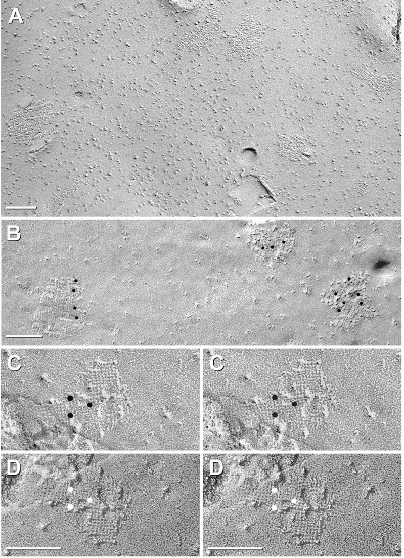
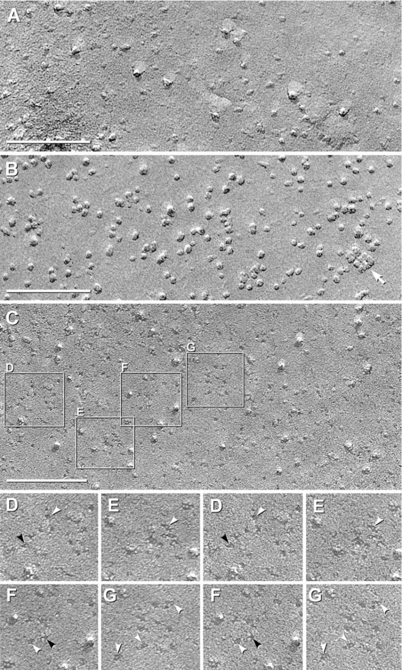
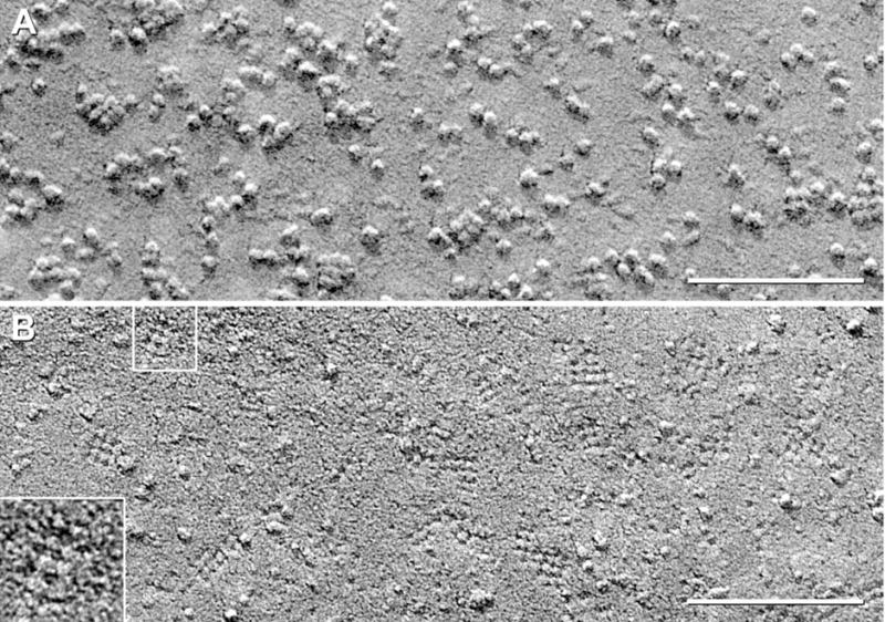
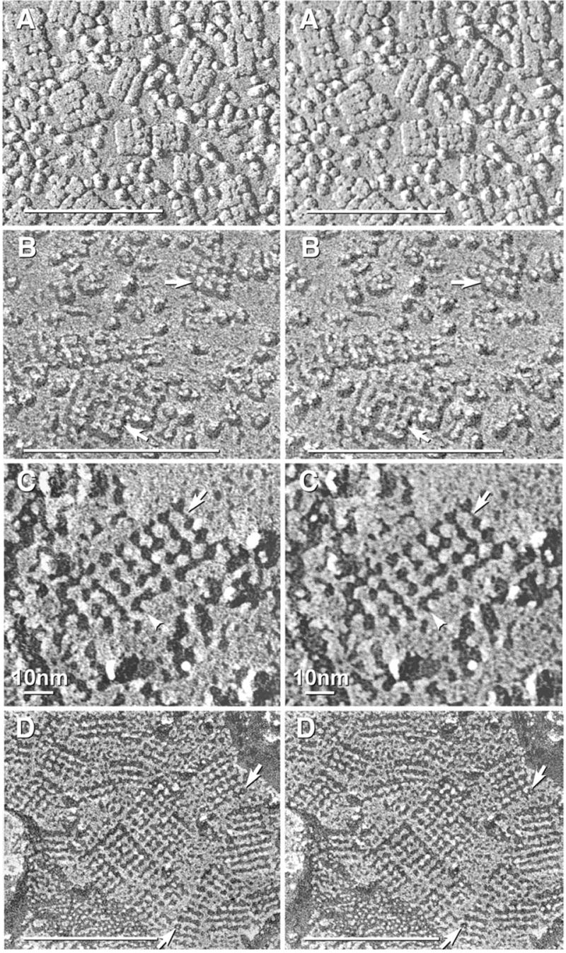
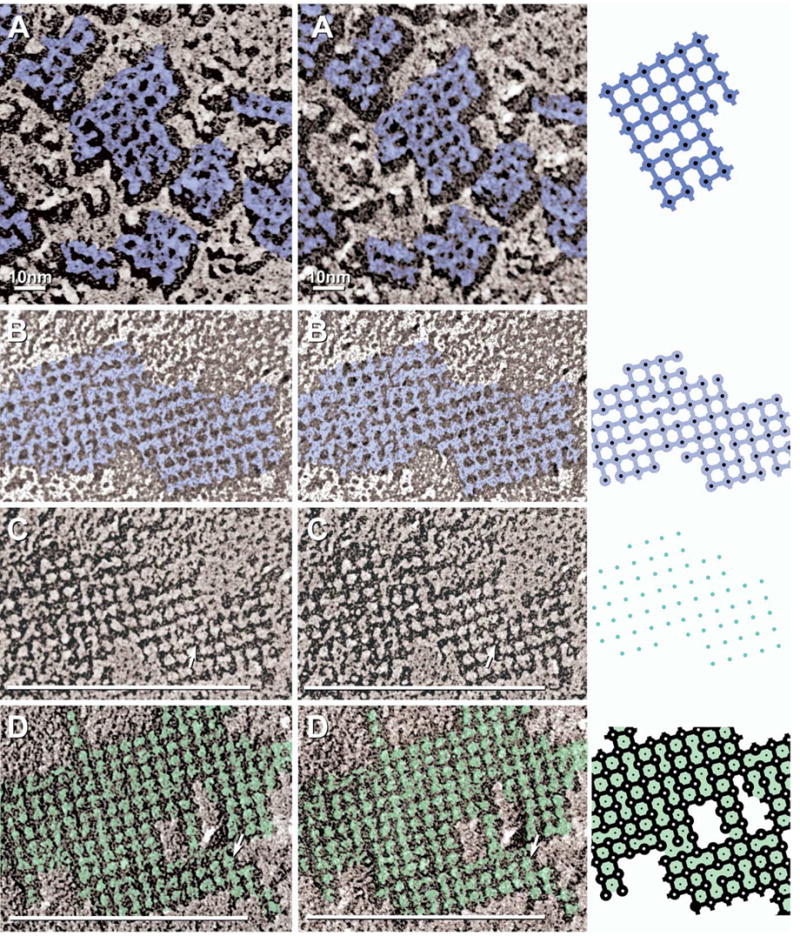
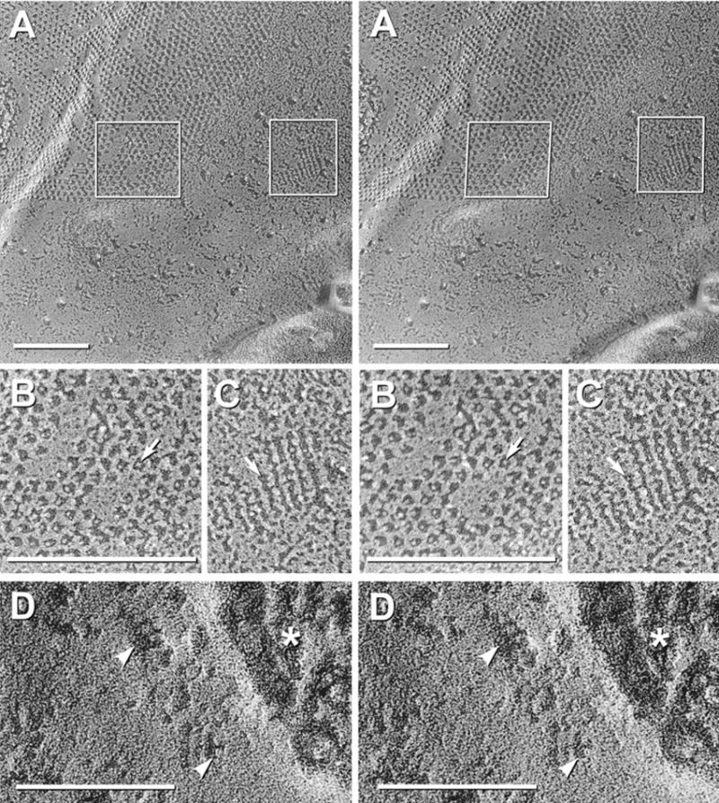
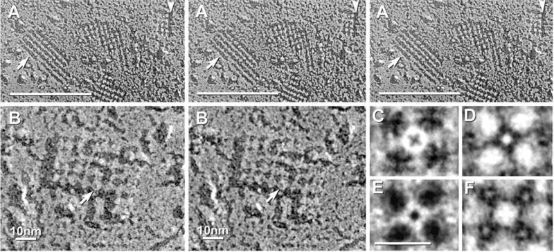
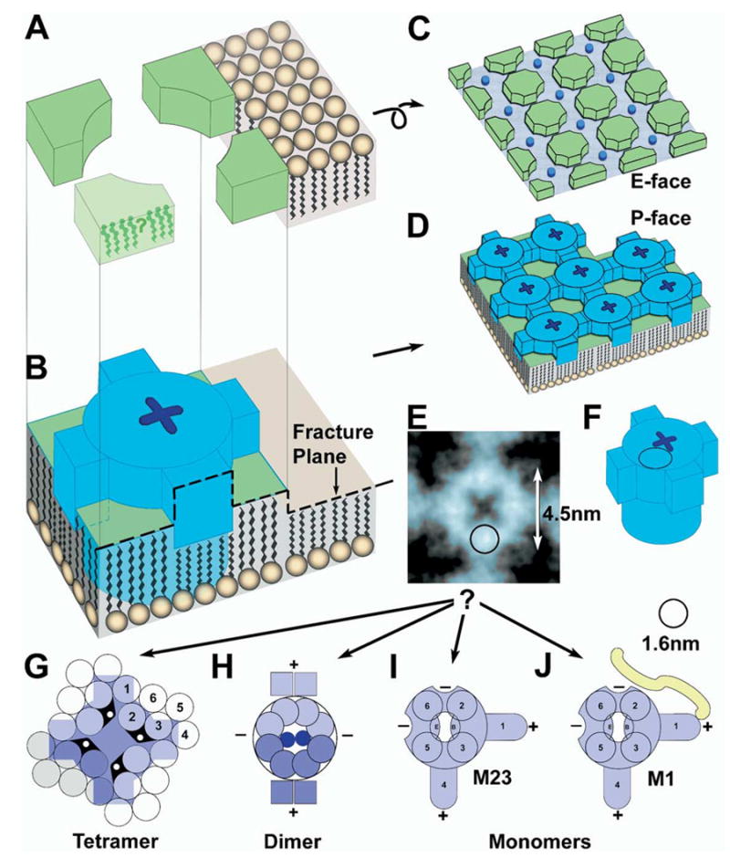
Each day, approximately 0.5-0.9 l of water diffuses through (primarily) aquaporin-1 (AQP1) channels in the human choroid plexus, into the cerebrospinal fluid of the brain ventricles and spinal cord central canal, through the ependymal cell lining, and into the parenchyma of the CNS. Additional water is also derived from metabolism of glucose within the CNS parenchyma. To maintain osmotic homeostasis, an equivalent amount of water exits the CNS parenchyma by diffusion into interstitial capillaries and into the subarachnoid space that surrounds the brain and spinal cord. Most of that efflux is through AQP4 water channels concentrated in astrocyte endfeet that surround capillaries and form the glia limitans. This report extends the ultrastructural and immunocytochemical characterizations of the crystalline aggregates of intramembrane proteins that comprise the AQP4 "square arrays" of astrocyte and ependymocyte plasma membranes. We elaborate on recent demonstrations in Chinese hamster ovary cells of the effects on AQP4 array assembly resulting from separate vs. combined expression of M1 and M23 AQP4, which are two alternatively spliced variants of the AQP4 gene. Using improved shadowing methods, we demonstrate sub-molecular cross-bridges that link the constituent intramembrane particles (IMPs) into regular square lattices of AQP4 arrays. We show that the AQP4 core particle is 4.5 nm in diameter, which appears to be too small to accommodate four monomeric proteins in a tetrameric IMP. Several structural models are considered that incorporate freeze-fracture data for submolecular "cross-bridges" linking IMPs into the classical square lattices that characterize, in particular, naturally occurring AQP4.


Figures

Fig. 1
Fig. 1
Square arrays in astrocyte endfeet of the glia limitans adjacent to the optic chiasm (A), in ependymocytes of the third ventricle near the suprachiasmatic nucleus (B–F), and in astrocyte processes in neuropil of adult rat spinal cord (G). (A) Stereoscopic image of area in which square arrays were in high density. Approximately 35% of arrays were immunogold labeled (10 nm gold beads). (B) Larger square arrays found in ependymocytes were most often labeled within the array perimeters, but occasionally, labels were 20–30 nm outside arrays (B, right side). (C–F) Higher magnification stereoscopic images of individual immunogold-labeled square arrays. The constituent IMPs within the 6.5 nm square lattices were 4.5 nm in diameter, with 1 × 2 nm cross-bridges linking adjacent IMPs. Many P-face IMPs had distinctive 1 nm central depressions or “dimples” (E, F, arrows). (G) Small-diameter astrocyte processes deep within neuropil in spinal cord of adult rat typically had multiple AQP4 square arrays. Immunogold beads labeled Cx30 (18 nm gold) and Cx26 (12 nm gold) in three gap junctions (middle gap junction is not visible at this tilt angle). In all images, unlabeled scale bars= 0.1 μm; labeled scale bars= 10 nm.
Fig. 2
Fig. 2
AQP4-M23 arrays in CHO cells. (A) Glutaraldehyde-fixed CHO cells expressing M23. Rafts represent large lattices of 4.5 nm-diameter IMPs, with many containing > 100 IMPs. (B–D) Formaldehyde-fixed CHO cell membranes that were immunogold labeled for AQP4. (B) Three “rafts” are labeled by four, three, and six 10 nm gold beads. (C, D) Stereoscopic images showing cross-bridges linking IMPs into a grid-like pattern. (D) Black shadow image more clearly reveals cross-bridges; IMPs are at intersections. Finer details are resolvable only at higher magnification (see Figs. 5–7, below).
Fig. 3
Fig. 3
Black shadow images of E-face of control CHO cells (A) and P- and E-face images of CHO cells expressing M1 variant of AQP4 (B–G). (A) E-face image of control CHO cell has “baseline” number of large particles but very few 4.5 nm diameter pits. (B) P-face image of M1 expressing cell has abundant 4–6 nm diameter IMPs, and in this area, only one square array (arrow). (C) E-face of CHO cell expressing M1. A large increase in 4.5–5 nm pits is observed above “control” value. Selected areas are shown stereoscopically at higher magnification (D–G). (D–G) Pegs are seen in most pits (white arrowheads). Many pits exhibit 1×2 nm “furrows,” frequently oriented at right angles (D, F; black arrowheads).
Fig. 4
Fig. 4
P- and E-face views of CHO cells co-expressing M1+M23. (A) P-face images reveal abundant but small square arrays. (B) E-face images of square array imprints. Pegs are visible in almost all pits. Many pits are linked by furrows, but up to 50% of furrows are missing. Inset shows array of seven pits linked by about four cross-bridges, but excessive granularity of this replica prevented more detailed analysis.
Fig. 5
Fig. 5
Stereoscopic images comparing “conventional” (A) and higher-resolution replicas of AQP4 square arrays (B–D). (A) In “old-style” replicas, IMPs are enlarged by excess platinum and by water vapor “contamination.” (B) In replicas made with ca. 1 nm of platinum, P-face images of AQP4 square arrays reveal 4.5 nm diameter IMPs linked by indistinct cross-bridges (at lower arrow). Some IMPs have indistinct “dimples” (arrows). (C) In E-face images, imprints of square arrays consist of 4.0–4.5 nm membrane “pits,” with most pits containing a central 0.7 nm central “peg” (faintly resolved). Each pit is linked to its nearest neighbors by 1×2 nm grooves or “furrows” (arrow). Some furrows at the edge of arrays (arrowhead) extend outward for possible attachment of additional IMPs/pits. Stereoscopic imaging reveals that the replicated P-face cross-bridges and E-face furrows are co-planar with the platinum replica and thus do not represent artifacts of underfocus or overfocus, which otherwise appear as a superimposed three-dimensional “fog.” (D) E-face imprints of square arrays in astrocyte endfoot in adult rat spinal cord. Pegs (arrows) are present in most E-face pits, and most pits are linked by 1×2 nm furrows.
Fig. 6
Fig. 6
High magnification stereoscopic images of AQP4 IMPs (A) and E-face pits (B–D), with corresponding drawings (right column). Color is used to delineate structures with similar electron opacities. (A) Black-shadow image of P-face AQP4 square array IMPs (dark blue) linked by 1×2 nm cross-bridges. (B, C) White-shadow (B) and black-shadow images (C) of square array E-face imprints (light blue in B) showing furrows linking membrane pits. Most pits contain a 0.3–0.7 nm “peg” (C; arrow; blue dots in diagram). (D) E-face image of M23 raft in CHO cell. Pits are linked by furrows and are separated by 4.5–5.0 nm “nodes” (arrow; green shading).
Fig. 7
Fig. 7
Comparison of two-fold difference in diameter of pegs in E-face pits of gap junctions and AQP4 arrays; and evidence for disappearance of pegs following shallow “etching.” (A) Stereoscopic image of gap junction and several square arrays in ependymocyte of third ventricle in adult rat suprachiasmatic nucleus. Boxed areas are enlarged in B and C. (B) Pegs in gap junction E-face pits (arrow) are 1.0–1.5 nm in diameter. (C) Pegs in square array E-face pits (arrow) are 0.3–0.7 nm in diameter, or about half the size of pegs in adjacent connexon imprints. (D) E-face image of square arrays after brief freeze etching. Etching is evident in extracellular space (asterisk). Where E-face pits are wider and deeper, pegs are missing (arrowheads), but nodes are intact.
Fig. 8
Fig. 8
(A) Stereoscopic (left pair) and reverse stereoscopic images (right pair) of square arrays in E-face showing that the “nodes” are fractured at a lower level than the surrounding membrane E-face. In “intaglio” images (right pair), this relative elevation is reversed so that the “nodes” artificially appear as raised “waffles.” (B) High-magnification stereoscopic image of one AQP4 square array. Several IMPs have central depressions or “dimples” (arrow). (C) Rotational reinforcement image of the IMP indicated in “B.” The central depression appears as an “X.” (D, E) Rotational reinforcement images of E-face pits printed with black shadows (D) and white shadows (E). In the black-shadow image (D), the peg (bright spot) is smaller than the dimple in the adjacent P-face IMP (C). In the white shadow image (E), the (now white) pit appears almost identical to the IMP in the black shadow image (C). Four nodes around the central peg (D, E) are approximately the same diameter as P-face IMPs, indicating that both nodes and IMPs each occupy approximately 50% of the cross-sectional area within a square array. (F) Rotational reinforcement of “node” showing reinforcement of four surrounding “pegs” (bright spots within darker E-face pits).
Fig. 9
Fig. 9
Interpretive drawings of components of naturally occurring square arrays and their constituent IMPs. (A, B) Fracture plane through an individual IMP, with the resulting formation of E-face (C) and P-face (D) images of a square array. Dark blue indicates an individual AQP4 IMP (B and D), with “X-shaped dimple.” (E, F) Approximate comparison of rotationally reinforced image on one IMP (E) with stylized AQP4 protein (F). Superimposed circles in remaining drawings are the approximate diameter of an α-helix, 1.6 nm, prior to platinum coating. A single α-helix is almost half the diameter of an AQP4 particle. (G–J) Comparison of tetrameric (G), dimeric (H), and monomeric (I) models of AQP4 IMP. The IMP seen by freeze fracture (blue in E) is much smaller than the 24 transmembrane α-helices required of a tetrameric IMP. (H) The dimeric model of AQP4 has conflicting positions for several α-helices. (I, J) Monomeric models for M23 (I) and M1 (J) AQP4. Two cross-bridges (“+”) are envisioned to arise from amphipathic α-helices (S1 and perhaps S4), while two additional cross-bridge binding sites (“−”) are envisioned as part of the core IMP, thereby providing for up to four cross-bridge binding sites per IMP. The additional 23 amino acid sequence on M1 (J) is proposed to interfere with close approach of M1 monomers to other monomers, and perhaps also to block additional cross-bridge binding sites.

References

    1. Agre P, King LS, Yasui M, Guggino WB, Ottersen OP, Fujiyoshi Y, Engel A, Nielsen S. Aquaporin water channels-from atomic structure to clinical medicine. J Physiol. 2002;542:3–16. - PMC - PubMed
    1. Agre P, Preston GM, Smith BL, Jung JS, Raina S, Moon C, Guggino WB, Nielsen S. Aquaporin CHIP: the archetypal molecular water channel. Am J Physiol. 1993:F463–F476. - PubMed
    1. Amiry-Moghaddam M, Ottersen OP. The molecular basis of water transport in the brain. Nat Rev Neurosci. 2003;4:991–1002. - PubMed
    1. Amiry-Moghaddam M, Xue R, Haug F-M, Neely JD, Bhardwaj A, Agre P, Adams ME, Froehner SC, Mori S, Ottersen OP. Alpha-syntrophin deletion removes the perivascular but not endothelial pool of aquaporin-4 at the blood-brain barrier and delays the development of brain edema in an experimental model of acute hyponatremia. FASEB J. 2004;18:542–544. - PubMed
    1. Anders JJ, Brightman MW. Assemblies of particles in the cell membranes of developing, mature, and reactive astrocytes. J Neurocytol. 1979;8:777–795. - PubMed

Publication types

MeSH terms

LinkOut - more resources