

Review
doi: 10.1136/jcp.2004.020271.
Analysis of prosthetic cardiac devices: a guide for the practising pathologist
Affiliations
- PMID: 15677529
- PMCID: PMC1770567
- DOI: 10.1136/jcp.2004.020271
Item in Clipboard
Review
Analysis of prosthetic cardiac devices: a guide for the practising pathologist
J Clin Pathol.
2005 Feb.
Abstract
Pathologists all over the world increasingly encounter prosthetic cardiac devices. A good evaluation of these devices is a valuable source of information, which can contribute to patient care and the appreciation and understanding of the pathobiology involved in the changes occurring between the host and the implanted prosthetic device. This article summarises the considerations underlying the analysis of prosthetic devices (particularly prosthetic heart valves), including the identification of the devices, the major morphological features of the devices, their modes of failure, and some technical details about evaluation and pitfalls.
Figures
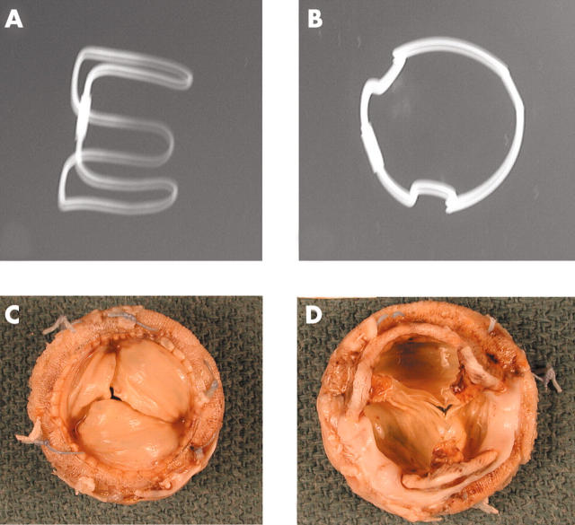
Anteroposterior and lateral x rays of a Carpentier-Edwards porcine bioprosthesis. (C) The flow surface and (D) the non-flow surface of a Carpentier-Edwards porcine valve. The cusps are pliable and intact. However, all three commissural regions show detachment from the stent posts.
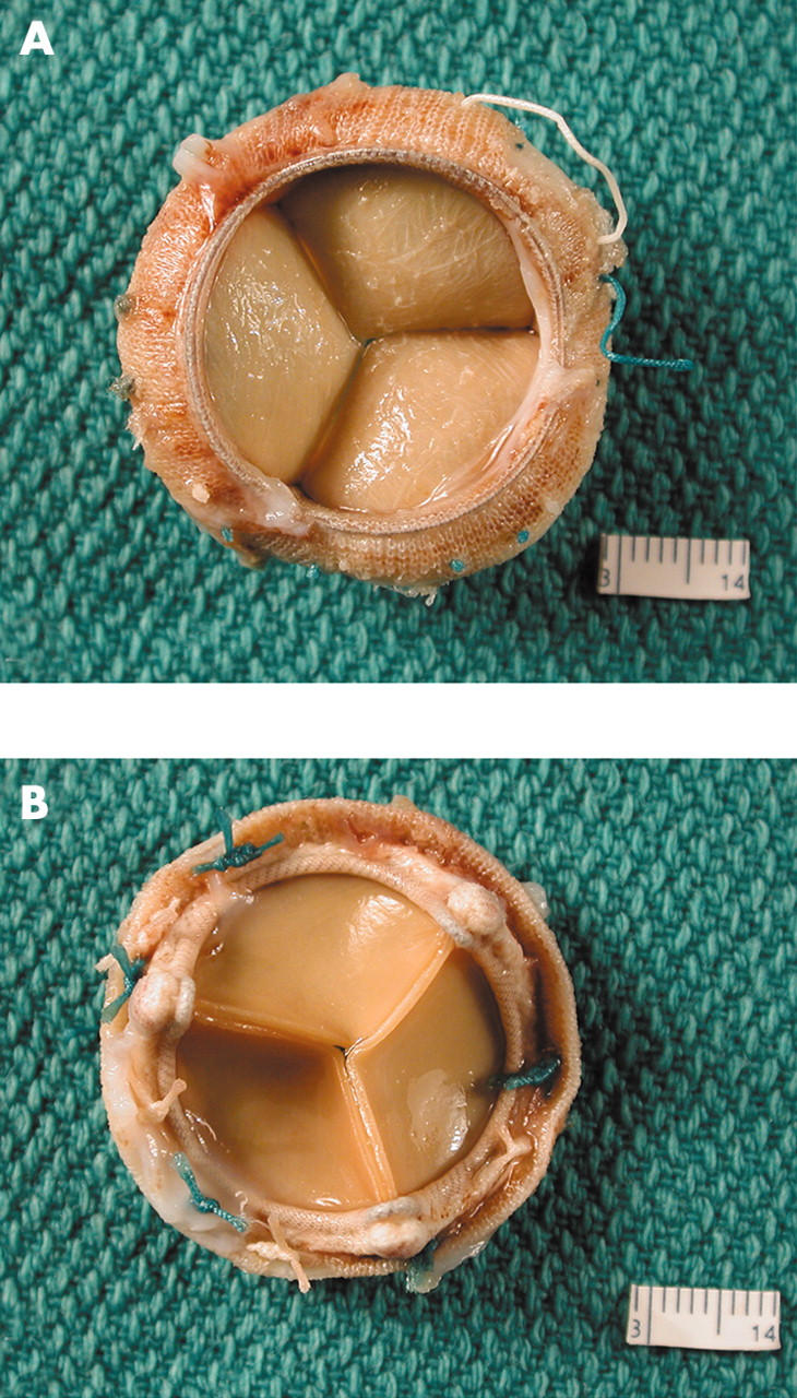
(A) The flow surface and (B) the non-flow surface of a Carpentier-Edwards pericardial bioprosthesis. The cusps are soft, pliable, intact, and they co-apt well.
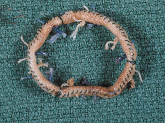
A soft Edwards-Physio annuloplasty ring. It has a soft, synthetic core covered with synthetic fabric.
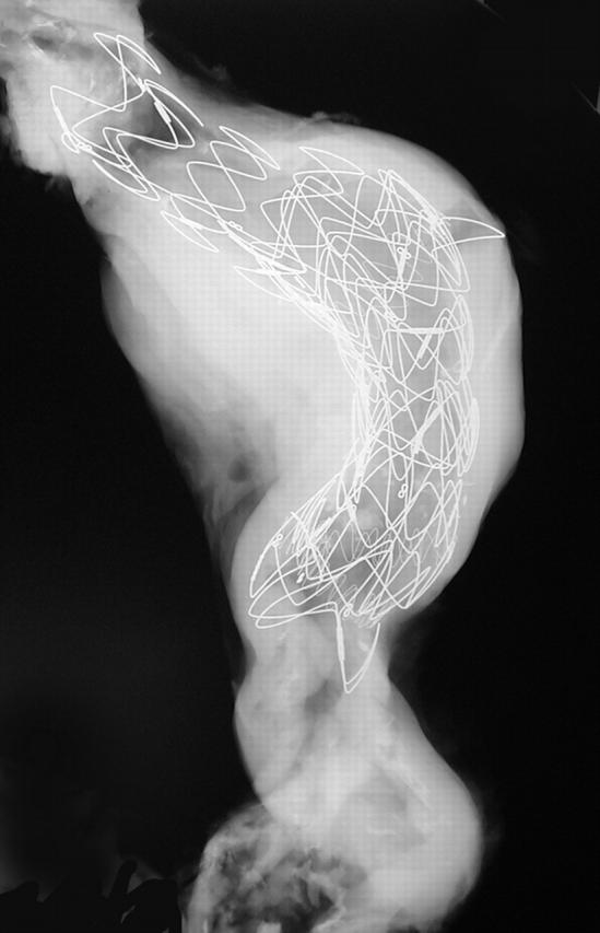
x Ray of an abdominal aorta shows a large stent in place. The most proximal segment shows an open cone (the rest of the stent is lined by fabric).
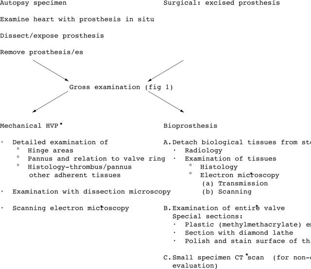
Gross examination of prosthetic heart devices: essential steps.
Detailed examination of prosthetic heart valves. *For special investigations only. Adapted from Schoen. CT, computed tomography.
(A) Anteroposterior and (B) lateral x rays of a Starr-Edwards mechanical valve (Model 1000) shows the intact “three leg cage”. (C) Flow surface and (D) non-flow surface of a “four leg cage” Starr-Edwards (Model 6400) valve. The struts are intact and the occluder (or poppet) has a pale yellow/brown colour. The non-flow surface shows tissue (arrows) still adherent to the sewing cuff.
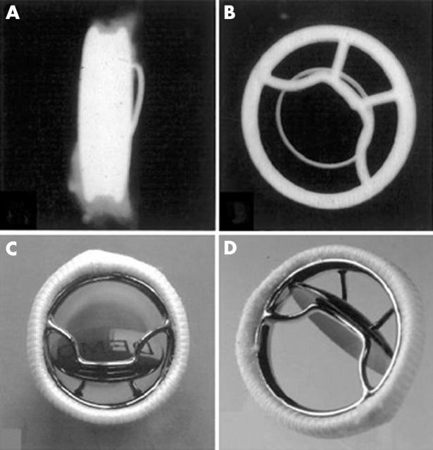
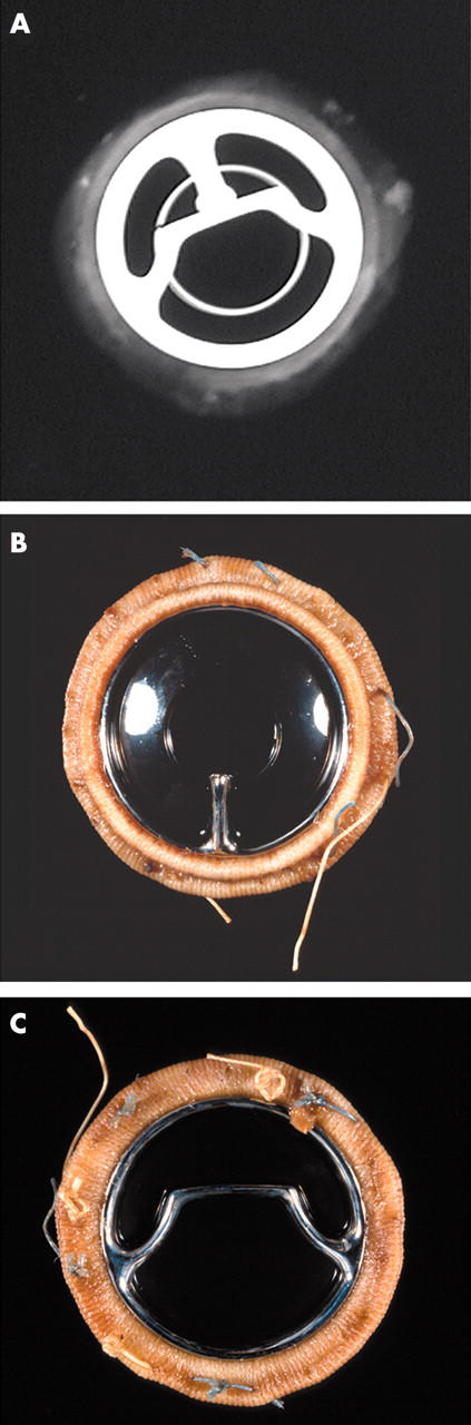
Bjork-Shiley concavo-convex valve. (A) x Ray of profile (lateral) view and (B) anteroposterior view showing the large (inflow) strut and the small (outflow) strut. Gross appearance of the valve; (C) valve partially closed with the disc in the oblique position and (D) valve open (disc or occluder is nearly vertical).
(A) x Ray (anteroposterior) of a Bjork-Shiley Monostrut valve. (B) Outflow surface showing the single outflow strut and (C) inflow surface of the Bjork-Shiley monostrut valve. The struts and the disc are intact.
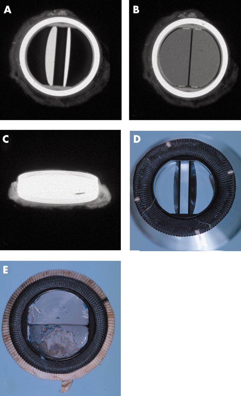
(A–C) x Rays of a Carbomedics bileaflet valve prosthesis with the discs open, discs closed, and profile of the prosthesis, respectively; x rays also show the radio opaque prosthesis housing. (D) The flow surface (discs open) and (E) the non-flow surface of the Carbomedics bileaflet prosthesis. The flow and non-flow surfaces of the sewing cuff are carbon coated (black).
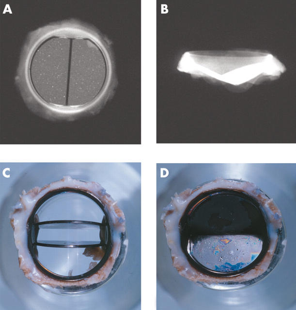
(A, B) x Rays of the flow surface and profile of the St Jude Medical bileaflet prosthesis. Views of a St Jude Medical bileaflet prosthesis with (C) the leaflets open and (D) the leaflets closed. A thick layer of grey/white pannus is seen on the flow and the non-flow surfaces of the sewing ring.
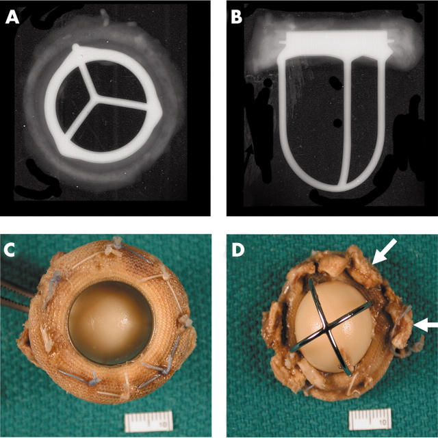
(A, B) Anteroposterior and lateral x rays of a Hancock porcine valve show a radio opaque valve ring and small eyelets in each of the stent posts. (C) The flow surface and (D) the non-flow surface of the porcine valve. The cusps are soft, pliable, and intact.
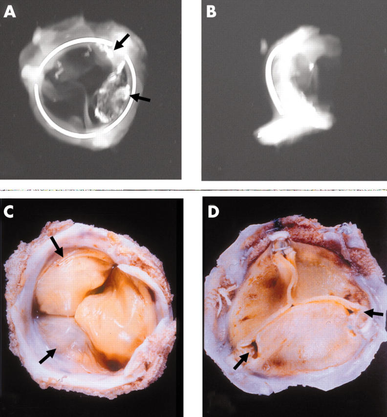
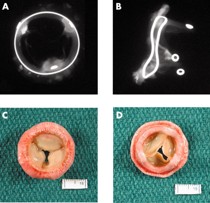
Anteroposterior and lateral x rays of an Ionescu-Shiley pericardial bioprosthesis showing the valve ring in three parts. Two of the three cusps show radio opaque areas of calcification (arrows). (C) The flow surface and (D) the non-flow views of an Ionescu-Shiley bovine pericardial valve. Pannus (arrows) is seen on the flow surface.
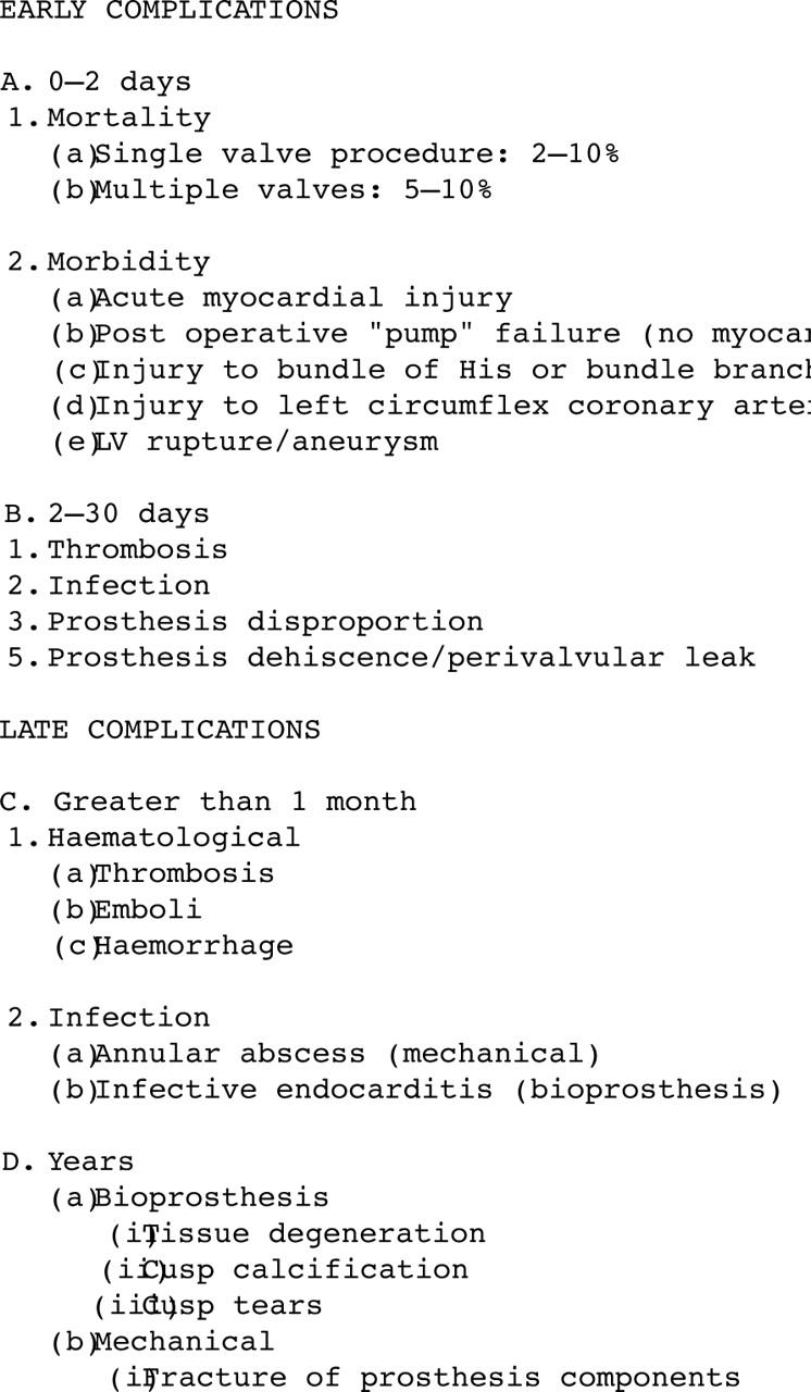
Early and late postoperative complications of prosthetic heart valves. LV, left ventricle.
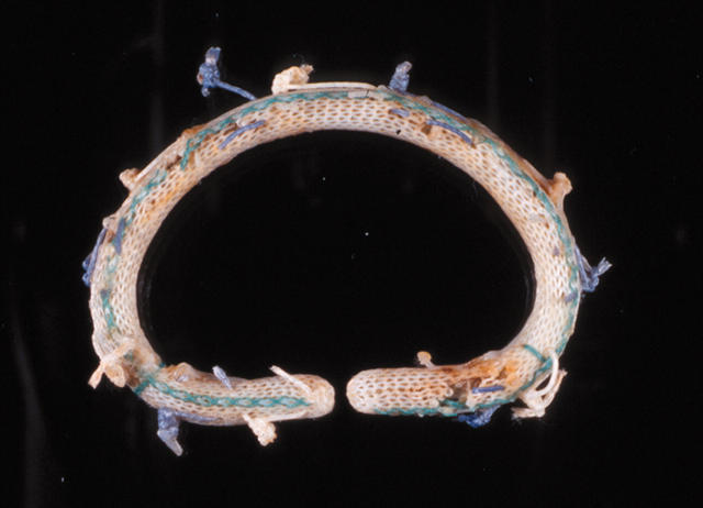
A Carpentier-Edwards annuloplasty ring. This D shaped ring has a hard metal core.
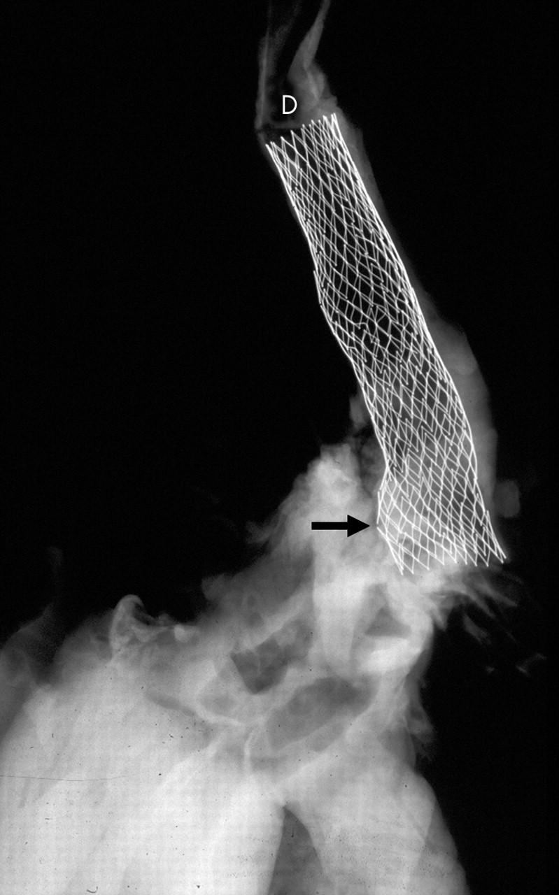
x Ray of an aortic arch and descending segment with a stent in place (D). Two of the stent struts show fractured segments (arrow).
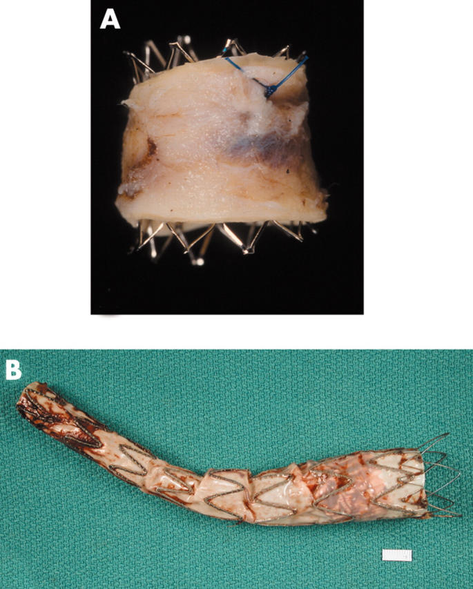
(A) An open (no fabric) stent in an aorta that had a co-arctation treated with this stent. (B) An aortic stent or endograft, showing the fabric lining the stent (on its inside (luminal) surface).
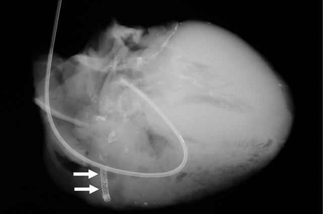
A heart obtained at necropsy shows stents in a right coronary artery (arrows). The left coronary artery shows extensive calcification. A Swan-Ganz catheter is seen in the right side of the heart (right atrium, right ventricle, and pulmonary artery).
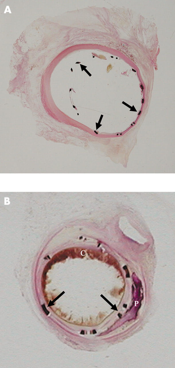
(A) Segment of coronary artery with a stent in place and embedded in GMMA, sectioned with a special lathe, surface polished, and stained with haematoxylin and eosin. This stent was in place for two weeks. The stent struts (arrows) and their relation to the vessel wall are seen. A minimal tissue reaction is seen focally. (B) This intracoronary stent was in place for seven weeks and was processed in the same manner as the stent in panel A. The stent struts are well placed and a good lumen is still evident. A circumferential tissue reaction is seen. Atherosclerotic plaque, blood clot (C), and calcification (P) are also seen.
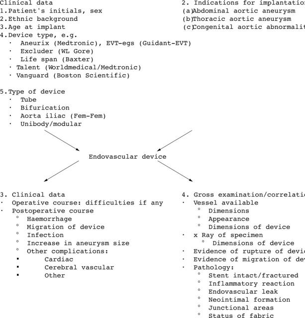
Examination of endovascular devices: stents for aortic aneurysm repair.
Similar articles
-
The failure modes of biological prosthetic heart valves.J Long Term Eff Med Implants. 2001;11(3-4):115-35. J Long Term Eff Med Implants. 2001. PMID: 11921659 Review.
-
[Progress in prosthetic heart valves].Nihon Rinsho. 1986 Jul;44(7):1698-707. Nihon Rinsho. 1986. PMID: 3531626 Review. Japanese. No abstract available.
-
The influence of design on bioprosthetic valve durability.J Long Term Eff Med Implants. 2001;11(3-4):137-49. J Long Term Eff Med Implants. 2001. PMID: 11921660 Review.
-
Haemodynamic evaluation of the Hancock bovine pericardial heart valve.Z Kardiol. 1986;75 Suppl 2:241-4. Z Kardiol. 1986. PMID: 3727694 No abstract available.
-
Are bioprostheses superior to mechanical valves?Z Kardiol. 1986;75 Suppl 2:286-8. Z Kardiol. 1986. PMID: 3727703
Cited by
-
Biocompatibility and biofilm inhibition of N,N-hexyl,methyl-polyethylenimine bonded to Boston Keratoprosthesis materials.Biomaterials. 2011 Dec;32(34):8783-96. doi: 10.1016/j.biomaterials.2011.08.010. Epub 2011 Sep 7. Biomaterials. 2011. PMID: 21903257 Free PMC article.
-
Material Safety of Styrene-Block-Ethylene/Butylene-Block-Styrene Copolymers Used for Cardiac Valves: 6-Month In Vivo Results from a Juvenile Sheep Model.Eur J Cardiothorac Surg. 2025 Aug 2;67(8):ezaf266. doi: 10.1093/ejcts/ezaf266. Eur J Cardiothorac Surg. 2025. PMID: 40748729 Free PMC article.
-
Pathology of the Aortic Valve: Aortic Valve Stenosis/Aortic Regurgitation.Curr Cardiol Rep. 2019 Jul 5;21(8):81. doi: 10.1007/s11886-019-1162-4. Curr Cardiol Rep. 2019. PMID: 31278595 Review.
-
Trends in complications of cardiac and vascular prosthetic devices, implants, and grafts mortality rate in the United States (1999-2020).Ann Med Surg (Lond). 2025 Jan 9;87(1):234-241. doi: 10.1097/MS9.0000000000002850. eCollection 2025 Jan. Ann Med Surg (Lond). 2025. PMID: 40109635 Free PMC article. Review.
References
-
- Rahimtoola SH. Vasodilator therapy in chronic severe aortic regurgitation. J Am Coll Cardiol 1990;16:430–2. - PubMed
-
- Schoen FJ. Approach to the analysis of cardiac valve prostheses as surgical pathology or autopsy specimens. Cardiovasc Pathol 1995;4:241–55. - PubMed
-
- Savage R . New law to require medical device injury reports. CAP Today 1991;40.
-
- Butany J, Fayet C, Ahluwalia MS, et al. Biological replacement heart valves. Identification and evaluation. Cardiovasc Pathol 2003;12:119–39. - PubMed
-
- Butany J, Ahluwalia MS, Munroe C, et al. Mechanical heart valve prostheses: identification and evaluation [erratum]. Cardiovasc Pathol 2003;12:322–44. - PubMed
Publication types
MeSH terms
LinkOut - more resources
Full Text Sources
Other Literature Sources