

Challenges and recent developments in hearing aids. Part I. Speech understanding in noise, microphone technologies and noise reduction algorithms
- PMID: 15678225
- PMCID: PMC4111442
- DOI: 10.1177/108471380400800302
Challenges and recent developments in hearing aids. Part I. Speech understanding in noise, microphone technologies and noise reduction algorithms
Abstract
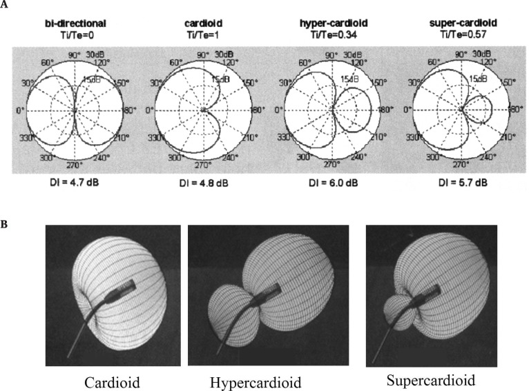
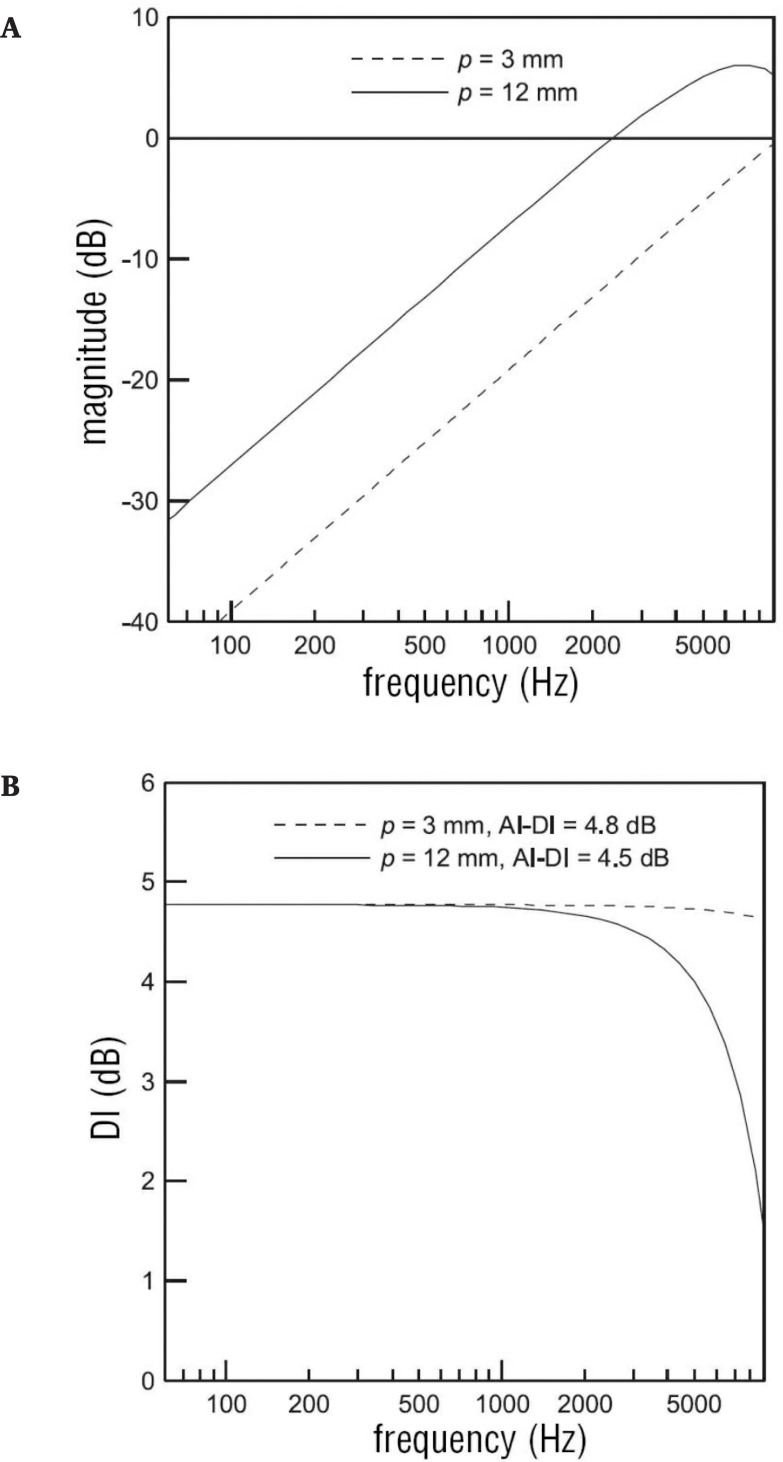
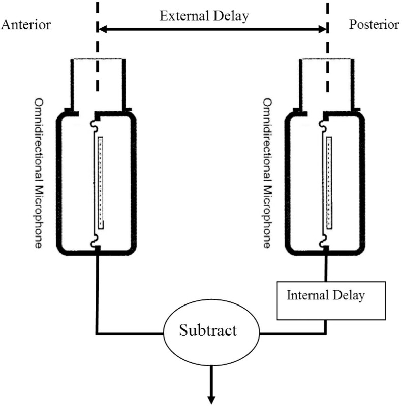
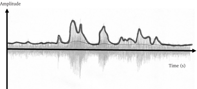
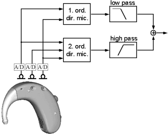
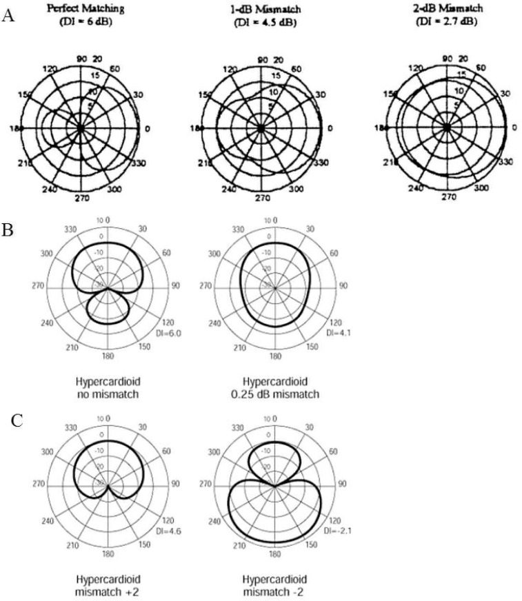
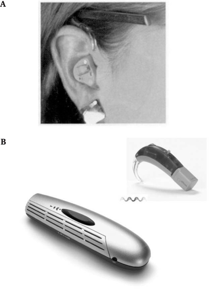
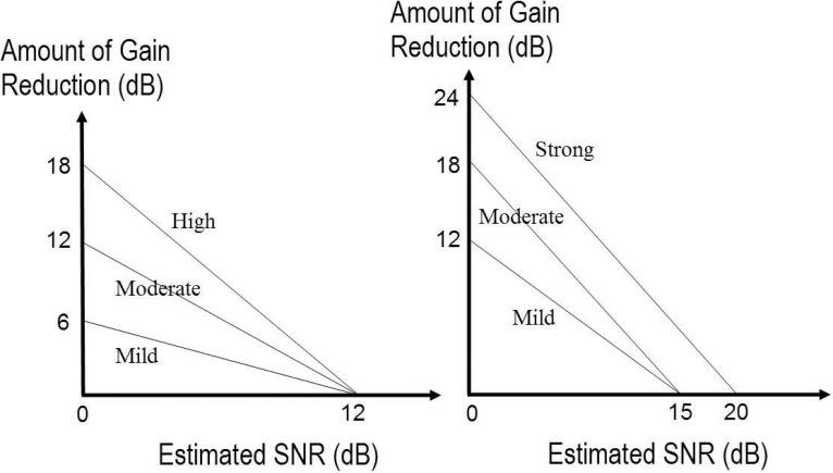
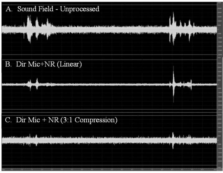
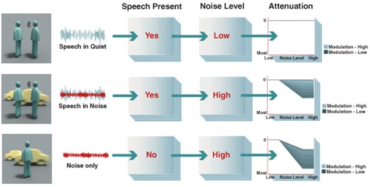
This review discusses the challenges in hearing aid design and fitting and the recent developments in advanced signal processing technologies to meet these challenges. The first part of the review discusses the basic concepts and the building blocks of digital signal processing algorithms, namely, the signal detection and analysis unit, the decision rules, and the time constants involved in the execution of the decision. In addition, mechanisms and the differences in the implementation of various strategies used to reduce the negative effects of noise are discussed. These technologies include the microphone technologies that take advantage of the spatial differences between speech and noise and the noise reduction algorithms that take advantage of the spectral difference and temporal separation between speech and noise. The specific technologies discussed in this paper include first-order directional microphones, adaptive directional microphones, second-order directional microphones, microphone matching algorithms, array microphones, multichannel adaptive noise reduction algorithms, and synchrony detection noise reduction algorithms. Verification data for these technologies, if available, are also summarized.
Figures
Similar articles
-
Noise reduction results of an adaptive filtering technique for dual-microphone behind-the-ear hearing aids.Ear Hear. 2004 Jun;25(3):215-29. doi: 10.1097/01.aud.0000130794.28068.96. Ear Hear. 2004. PMID: 15179113
-
Effects of directional microphone and adaptive multichannel noise reduction algorithm on cochlear implant performance.J Acoust Soc Am. 2006 Oct;120(4):2216-27. doi: 10.1121/1.2258500. J Acoust Soc Am. 2006. PMID: 17069317
-
Speech recognition in noise using bilateral open-fit hearing aids: the limited benefit of directional microphones and noise reduction.Int J Audiol. 2013 Jan;52(1):29-36. doi: 10.3109/14992027.2012.707335. Epub 2012 Aug 29. Int J Audiol. 2013. PMID: 22928919
-
[New developments in hearing aid technology].Ther Umsch. 2004 Jan;61(1):35-9. doi: 10.1024/0040-5930.61.1.35. Ther Umsch. 2004. PMID: 14997998 Review. German.
-
Digital noise reduction: an overview.Trends Amplif. 2006 Jun;10(2):67-82. doi: 10.1177/1084713806289514. Trends Amplif. 2006. PMID: 16959731 Free PMC article. Review.
Cited by
-
Cross-Modal Sensory Boosting to Improve High-Frequency Hearing Loss: Device Development and Validation.JMIRx Med. 2024 Feb 9;5:e49969. doi: 10.2196/49969. JMIRx Med. 2024. PMID: 38345294 Free PMC article.
-
EEG-assisted Modulation of Sound Sources in the Auditory Scene.Biomed Signal Process Control. 2018 Jan;39:263-270. doi: 10.1016/j.bspc.2017.08.008. Epub 2017 Aug 16. Biomed Signal Process Control. 2018. PMID: 31118975 Free PMC article.
-
Neural Representation Enhanced for Speech and Reduced for Background Noise With a Hearing Aid Noise Reduction Scheme During a Selective Attention Task.Front Neurosci. 2020 Sep 10;14:846. doi: 10.3389/fnins.2020.00846. eCollection 2020. Front Neurosci. 2020. PMID: 33071722 Free PMC article.
-
Effects of Adaptation Rate and Noise Suppression on the Intelligibility of Compressed-Envelope Based Speech.PLoS One. 2015 Jul 21;10(7):e0133519. doi: 10.1371/journal.pone.0133519. eCollection 2015. PLoS One. 2015. PMID: 26196508 Free PMC article.
-
Extending the articulation index to account for non-linear distortions introduced by noise-suppression algorithms.J Acoust Soc Am. 2011 Aug;130(2):986-95. doi: 10.1121/1.3605668. J Acoust Soc Am. 2011. PMID: 21877811 Free PMC article.
References
-
- Agnew J. (1997). An overview of digital signal processing in hearing instruments. Hear Rev 4 (7): 8, 12,, 16,, 18,, 66
-
- Agnew J, Block M. (1997). HINT thresholds for dual-microphone BTE. Hear Rev 4 (26): 29–30
-
- Agnew J, Thornton JM. (2000). Just noticeable and objectionable group delays in digital hearing aids. J Am Acad Audiol 11 (6): 330–336 - PubMed
-
- American Academy of Audiology (2003). Pediatric Amplification Protocol. http://www.audiology.org/professional/positions/pedamp.pdf Last accessed Dec 2, 2004
-
- Amlani AM. (2001). Efficacy of directional microphone hearing aids: A meta-analytic perspective. J Am Acad Audiol 12 (4): 202–214 - PubMed
Publication types
MeSH terms
LinkOut - more resources
Full Text Sources
Other Literature Sources
Medical