. 2004 Spring;5(2):1-17.
doi: 10.1120/jacmp.v5i2.1975. Epub 2004 Apr 1.

Verification of inverse planning and treatment delivery for segmental IMRT

Affiliations

Verification of inverse planning and treatment delivery for segmental IMRT

James L Bedford et al. J Appl Clin Med Phys. 2004 Spring.

Abstract

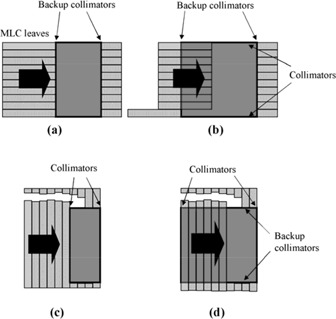
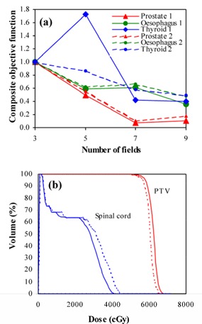
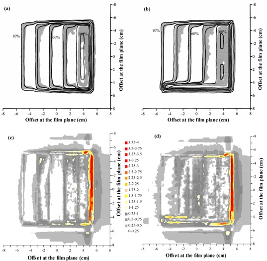
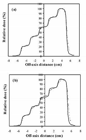
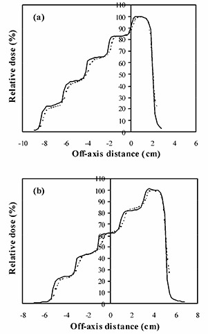
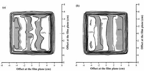
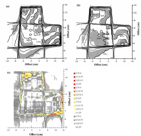
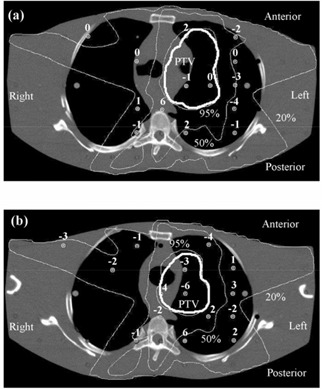
With intensity-modulated radiotherapy (IMRT), it is important that the inverse planning process yields the most appropriate dose distribution for the patient and that the delivered dose then corresponds to the planned dose. This paper presents methods by which the inverse planning and delivery of segmental (step-and-shoot) IMRT can be verified, and gives results for a typical treatment planning system (Pinnacle3 v6.2b, Philips Radiation Oncology Systems, Milpitas, CA). Inverse planning was assessed by observing the reduction in objective function as fields were successively added to three-field prostate, esophagus, and thyroid plans. The ability of the treatment planning system to calculate dose for a segmented field was examined by creating a stepped field with five successively narrowing segments. The complete planning process was then investigated by using two orthogonal IMRT fields to create a homogeneous dose distribution in a cubic water phantom. Finally, a clinical situation was simulated by creating a five-field segmental IMRT plan for a lung target in an anthropomorphic phantom. A conformal plan was also compared for context. Addition of fields to inverse plans generally resulted in a reduction of objective function, indicating consistency of inverse planning solutions. Planned dose for fields with stepped intensity agreed with ionization chamber measurements to within 5%. For orthogonal fields, planned dose distributions agreed well with dose measured using film and agreed with ionization chamber measurements to within 3%. For the anthropomorphic phantom, the standard deviation of difference between planned and measured dose was 4%. Although no consensus has yet been reached on what constitutes an acceptable IMRT plan, these results indicate that step-and-shoot IMRT can be planned and delivered using the system described with comparable accuracy to a standard conformal treatment.


Figures

Figure 1
Figure 1
Field configurations used for testing the dose calculation for segmented fields. In each case, there are five segments. In (a) and (b), modulation is parallel to the direction of MLC leaf motion, whereas in (c) and (d), modulation is perpendicular to the direction of MLC leaf motion. In (c) and (d), pairs of leaves are successively drawn completely across the field so as to narrow its width in the direction of the arrow. In (a) and (c), the segments are defined by both MLC leaves and collimators, whereas in (b) and (d), the segments are defined by MLC leaves only.
Figure 2
Figure 2
(a) Variation of composite objective function with different numbers of fields for equal starting beam weights (large symbols and solid lines) and with starting beam weights perturbed by 10% (small symbols and dashed lines). (b) Dose‐volume histograms for the five‐field thyroid plan, with equal starting beam weights (solid lines) and starting beam weights perturbed by 10% (dashed lines).
Figure 3
Figure 3
Comparison of calculated dose and dose measured using film for a single segmented field, with the modulation parallel to the direction of leaf motion. (a) Superposition of calculated (lines) and measured (gray scale) dose distributions, with the field defined by both MLC leaves and collimators. (b) Superposition of calculated (lines) and measured (gray scale) dose distributions, with the field defined by MLC leaves only. (c) Gamma distribution for criteria of 4% and 4 mm, with the field defined by both MLC leaves and collimators. (d) Gamma distribution for criteria of 4% and 4 mm, with the field defined by MLC leaves only. In (a) and (b), isodoses are at intervals of 10%, relative to the dose at the center of the high‐dose step. In (c) and (d), gray scale denotes those areas where the acceptance criteria are met.
Figure 4
Figure 4
Calculated dose profile (solid lines) and dose profile measured using film (broken lines) for a single segmented field, with the modulation parallel to the direction of leaf motion. (a) Field defined by both MLC leaves and collimators. (b) Field defined by MLC leaves only.
Figure 5
Figure 5
Calculated dose profile (solid lines) and dose profile measured using film (broken lines) for a single segmented field, with the modulation perpendicular to the direction of leaf motion. (a) Field defined by both MLC leaves and collimators. (b) Field defined by MLC leaves only.
Figure 6
Figure 6
Calculated dose (lines) and dose measured using film (gray scale) for (a) the field with gantry angle 0° and (b) the field with gantry angle 90°, in an IMRT plan consisting of orthogonal fields. Isodoses are at intervals of 10%, relative to the central axis dose.
Figure 7
Figure 7
Comparison of calculated dose and dose measured using film for an IMRT plan consisting of orthogonal fields. (a) Superposition of calculated (lines) and measured (gray scale) dose distributions for a transaxial plane at the isocenter. (b) Superposition of calculated (lines) and measured (gray scale) dose distributions for a transaxial plane 5 cm farther away from the gantry than the isocenter. (c) Gamma distribution for criteria of 4% and 4 mm, for a transaxial plane 5 cm farther away from the gantry than the isocenter. In (a) and (b), isodoses are at intervals of 10%, relative to the intersection of the beam axes. In (c), gray scale indicates those areas where the acceptance criteria are met.
Figure 8
Figure 8
Verification of a lung IMRT plan using TLD, showing transaxial planes (a) 1 cm inferior and (b) 1.5 cm superior to the isocentric plane. The dose differences represent the planned dose in relation to the delivered dose, expressed as a percentage of the isocentric dose. Isodoses are normalized to the isocenter.
Figure 9
Figure 9
Comparison of calculated dose and dose measured using film in a transaxial plane 0.4 cm superior to the isocenter for a lung IMRT plan. (a) Superposition of calculated (lines) and measured (gray scale) dose distributions for an IMRT plan. (b) Superposition of calculated (lines) and measured (gray scale) dose distributions for the corresponding conformal plan with the same beam orientations. (c) Gamma distribution for criteria of 4% and 4 mm, for an IMRT plan. (d) Gamma distribution for criteria of 4% and 4 mm, for the corresponding conformal plan with the same beam orientations. In (a) and (b), isodoses are at intervals of 10%, relative to the intersection of the beam axes. In (c) and (d), gray scale indicates those areas where the acceptance criteria are met.

References

    1. Webb S., Intensity‐modulated radiation therapy, Bristol: Institute of Physics Publishing, 2001.
    1. Xing L., Li J.G., Donaldson S., Le Q.T., and Boyer A.L., Optimization of importance factors in inverse planning, Phys. Med. Biol. 44, 2525–36 (1999). - PubMed
    1. Bedford J.L. and Webb S., Elimination of importance factors for clinically accurate selection of beam orientations, beam weights and wedge angles in conformal radiation therapy, Med. Phys. 30, 1788–804 (2003). - PubMed
    1. Clark C.H., Mubata C.D., Meehan C.A. et al., IMRT clinical implementation: Prostate and pelvic node irradiation using Helios and a 120‐leaf multileaf collimator, J. Appl. Clin. Med. Phys. 3 (4), 273–84 (2002). - PMC - PubMed
    1. Low D.A., Mutic S., Dempsey J.F. et al., Quantitative dosimetric verification of an IMRT planning and delivery system, Radiother. Oncol. 49, 305–16 (1998). - PubMed

Publication types

LinkOut - more resources