Comparative Study
. 2005 Apr;17(4):1167-79.
doi: 10.1105/tpc.104.029694. Epub 2005 Mar 16.

Structural basis of eukaryotic nitrate reduction: crystal structures of the nitrate reductase active site

Affiliations
Comparative Study

Structural basis of eukaryotic nitrate reduction: crystal structures of the nitrate reductase active site

Katrin Fischer et al. Plant Cell. 2005 Apr.

Abstract

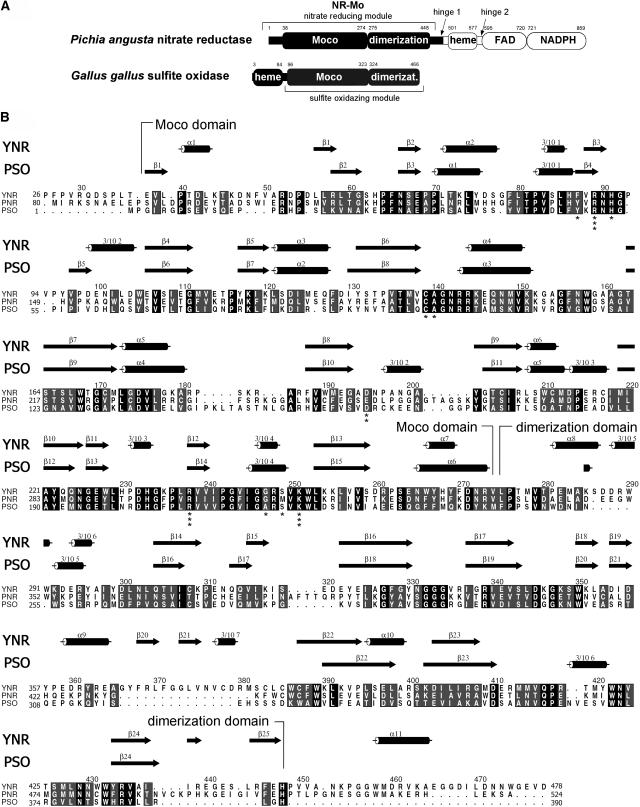
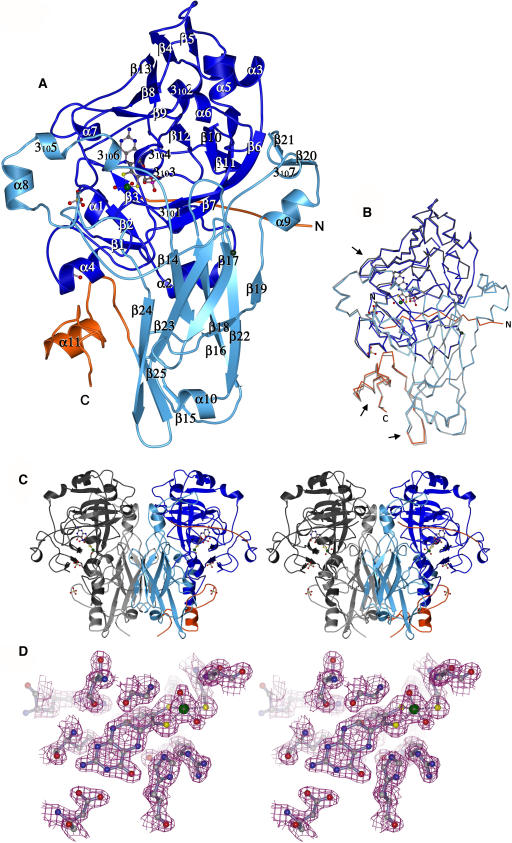
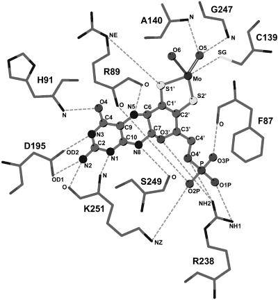
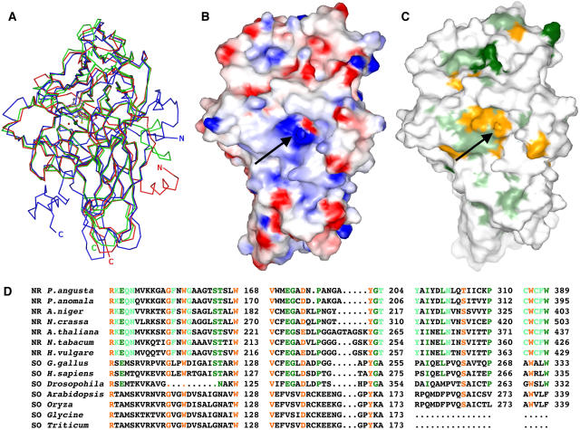
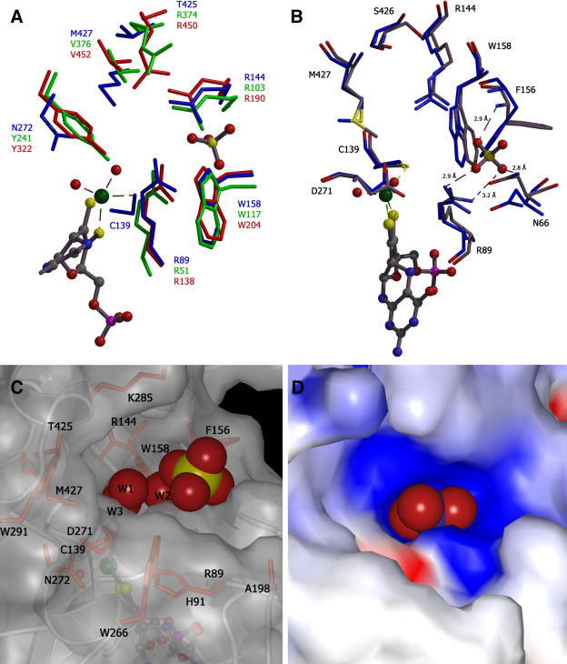
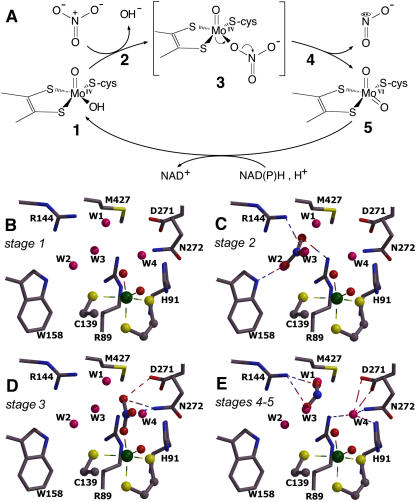
Nitrate assimilation in autotrophs provides most of the reduced nitrogen on earth. In eukaryotes, reduction of nitrate to nitrite is catalyzed by the molybdenum-containing NAD(P)H:nitrate reductase (NR; EC 1.7.1.1-3). In addition to the molybdenum center, NR contains iron-heme and flavin adenine dinucleotide as redox cofactors involved in an internal electron transport chain from NAD(P)H to nitrate. Recombinant, catalytically active Pichia angusta nitrate-reducing, molybdenum-containing fragment (NR-Mo) was expressed in P. pastoris and purified. Crystal structures for NR-Mo were determined at 1.7 and 2.6 angstroms. These structures revealed a unique slot for binding nitrate in the active site and identified key Arg and Trp residues potentially involved in nitrate binding. Dimeric NR-Mo is similar in overall structure to sulfite oxidases, with significant differences in the active site. Sulfate bound in the active site caused conformational changes, as compared with the unbound enzyme. Four ordered water molecules located in close proximity to Mo define a nitrate binding site, a penta-coordinated reaction intermediate, and product release. Because yeast NAD(P)H:NR is representative of the family of eukaryotic NR, we propose a general mechanism for nitrate reduction catalysis.


Figures

Figure 1.
Figure 1.
Primary and Secondary Structure Comparison of NR and SO. (A) Domain structure of P. angusta NR and CSO. The NR-Mo fragment that has been expressed, purified, and crystallized is shown in black. The first and last residues of conserved domains (Moco binding, dimerization, heme, FAD, and NADPH binding domains) are indicated. (B) Sequence alignment of yeast NR (P. angusta, YNR) and Arabidopsis NR2 (plant NR, PNR) with Arabidopsis SO (plant SO, PSO). Strictly conserved residues are highlighted in black, and conserved residues are highlighted in gray. Secondary structure elements for YNR and PSO are shown above the alignment with cylinders for α- or 310-helices and arrows for β-sheets. The alignment was generated with ClustalW (Thompson et al., 1994) and ALSCRIPT (Barton, 1993). Secondary structure elements were determined with PROMOTIF (Hutchinson and Thornton, 1996). Residue numbering is based on the primary sequence of YNR. Residues of NR-Mo that coordinate the Moco are indicated with asterisks. The number of asterisks correlates with the number of contacts to Moco.
Figure 2.
Figure 2.
Overall Structure of NR-Mo. (A) Ribbon presentation of the NR-Mo monomer. The two domains are colored dark blue (Moco domain) and light blue (dimerization domain), and the nonconserved N-terminal part and the C-terminal linker region is colored orange. The Moco, Na+, and sulfates are shown in ball-and-stick representation, β-strands as curved arrows, and α- and 310-helices as ribbons. The bonds between Mo and all five ligands are plotted as dashes (cf. [D]). The model is a composite of residues 26 to 70 from NR-Mo1 and residues 71 to 478 from NR-Mo2. (B) Superposition of NR-Mo1 and NR-Mo2 monomers. NR-Mo1 is colored and orientated as in (A); NR-Mo2 is shown in gray. (C) Stereo view of the NR-Mo dimer in ribbon presentation (merged as in [A]). For one monomer, the color coding is the same as in (A), and the second monomer is shown in dark and light gray. (D) Stereo close-up view of Moco and coordinating residues shown in ball-and-stick representation, with dashed bonds between Mo and its five ligands. The 2Fo-Fc electron density map is contoured at 1.0 σ. The figure was generated with MOLSCRIPT (Esnouf, 1997) and rendered with POVRAY (www.povray.org).
Figure 3.
Figure 3.
The Coordination of the Moco. Schematic representation of all protein–Moco interactions. Hydrogen bonds are drawn as dashed lines. No water-mediated hydrogen bonds between the Moco and protein were observed. The hydroxy coordination of the equatorial Mo-bound oxygen (O6) is indicated by a bold solid line and the oxo-coordination of the apical oxygen (O5) by duplicate lines. Figure was generated with LIGPLOT (Wallace et al., 1995).
Figure 4.
Figure 4.
Comparisons between NR-Mo and SOs. (A) Superposition of NR-Mo fragments from P. angusta NR (blue), PSO (green), and CSO (red). The figure was generated as described in Figure 2. (B) Electrostatic surface potential of NR-Mo. Surface residues are color coded according to their charge (blue for positively charged and red for negatively charged side chains). Hydrophobic areas are not colored. The view is toward the entrance of the substrate funnel (arrow). The electrostatic potential map was calculated at an ionic strength of 100 mM and contoured at ±10 kBT (kB, Boltzmann constant; T, absolute temperature). (C) and (D) Conserved residues among enzymes of the SO family are shown on the surface (C) and in an alignment (D). Residues that are identical (one outlier was excepted) among all NRs are shown in light green, those among NRs and animal SOs are shown in dark green, and those among the entire SO family of Mo enzymes (including both NRs and SOs) are shown in orange. Sequence alignments were generated with ClustalW, and the last residue of each sequence line is numbered. Surfaces were generated using GRASP (Nicholls et al., 1991) and rendered with POVRAY.
Figure 5.
Figure 5.
The Active Site of NR-Mo. (A) Superposition of the active sites of NR-Mo2, PSO, and CSO. Residues of NR-Mo are color coded in blue, PSO in green, and CSO in red. All residues are shown in stick mode and are numbered in the corresponding color. (B) Superposition of the active sites of NR-Mo1 (blue) and NR-Mo2 (gray). NR-Mo2 residues are colored in gray and NR-Mo1 in blue. In (A) and (B), Moco (derived from NR-Mo2) and sulfate are shown in ball-and-stick mode, and both panels were generated with MOLSCRIPT (Esnouf, 1997). (C) and (D) Surface representation of the substrate binding site of NR-Mo2 with the bound sulfate and three active site waters (W1-3) (C) and with nitrate superimposed onto the waters (D); all are shown as a space-filling model. Surfaces are shown either transparent with highlighted and labeled active site residues or nontransparent and color coded according to the surface charge as shown in Figure 4A. The surfaces were made as described in Figure 4.
Figure 6.
Figure 6.
Hypothetical Reaction Cycle of Nitrate Reduction by NR. (A) Reaction cycle of nitrate reduction by NR. The reaction starts with the reduced Mo(IV) center (stage 1). Nitrate binds to the active site (stage 2) and replaces the equatorial hydroxo/water ligand, thus forming the reaction intermediate (stage 3). Upon oxidation of the Mo center to Mo(VI), the bond between the nitrate oxygen and nitrogen is broken, and nitrite will be released (stages 4 and 5). After completion of the reductive half-reaction, the Mo is regenerated [Mo(IV)] for the next cycle. (B) to (E) Models of the active site at different stages of the reaction cycle, generated with MOLSCRIPT and rendered with RASTER3D (Merritt and Murphy, 1994). (B) View of the active site as seen in the 1.7-Å structure with four water molecules (W1 to W4) bound. The view resembles the situation shown in (A) at stage 1. (C) Hypothetical binding of nitrate based on a superposition with W2 and W3 (stage 2 in [A]). The nitrate oxygen located at W3 attacks the Mo, and the Mo hydroxo ligand will be displaced to the position of W4. (D) Formation of a penta-coordinated reaction intermediate with the nitrogen, nitrate-oxygen, Mo, and the apical oxygen forming a plane. The resulting hydrogen bonds of bound nitrate are indicated (stage 3 in [A]). (E) The released nitrite is superimposed with W1 and W2 because of the high mobility of W1 (B-factor = 46).

Similar articles

Cited by

References

    1. Bahadur, R.P., Chakrabarti, P., Rodier, F., and Janin, J. (2004). A dissection of specific and non-specific protein-protein interfaces. J. Mol. Biol. 336, 943–955. - PubMed
    1. Barbier, G.G., Joshi, R.C., Campbell, E.R., and Campbell, W.H. (2004). Purification and biochemical characterization of simplified eukaryotic nitrate reductase expressed in Pichia pastoris. Protein Expr. Purif. 37, 61–71. - PubMed
    1. Barton, G.J. (1993). ALSCRIPT: A tool to format multiple sequence alignments. Protein Eng. 6, 37–40. - PubMed
    1. Campbell, W.H. (2001). Structure and function of eukaryotic NAD(P)H:nitrate reductase. Cell. Mol. Life Sci. 58, 194–204. - PMC - PubMed
    1. Campbell, W.H., and Kinghorn, K.R. (1990). Functional domains of assimilatory nitrate reductases and nitrite reductases. Trends Biochem. Sci. 15, 315–319. - PubMed

Publication types

MeSH terms

LinkOut - more resources