. 2005 Jun;3(6):e150.
doi: 10.1371/journal.pbio.0030150. Epub 2005 May 3.

Antigen-engaged B cells undergo chemotaxis toward the T zone and form motile conjugates with helper T cells

Affiliations

Antigen-engaged B cells undergo chemotaxis toward the T zone and form motile conjugates with helper T cells

Takaharu Okada et al. PLoS Biol. 2005 Jun.

Abstract

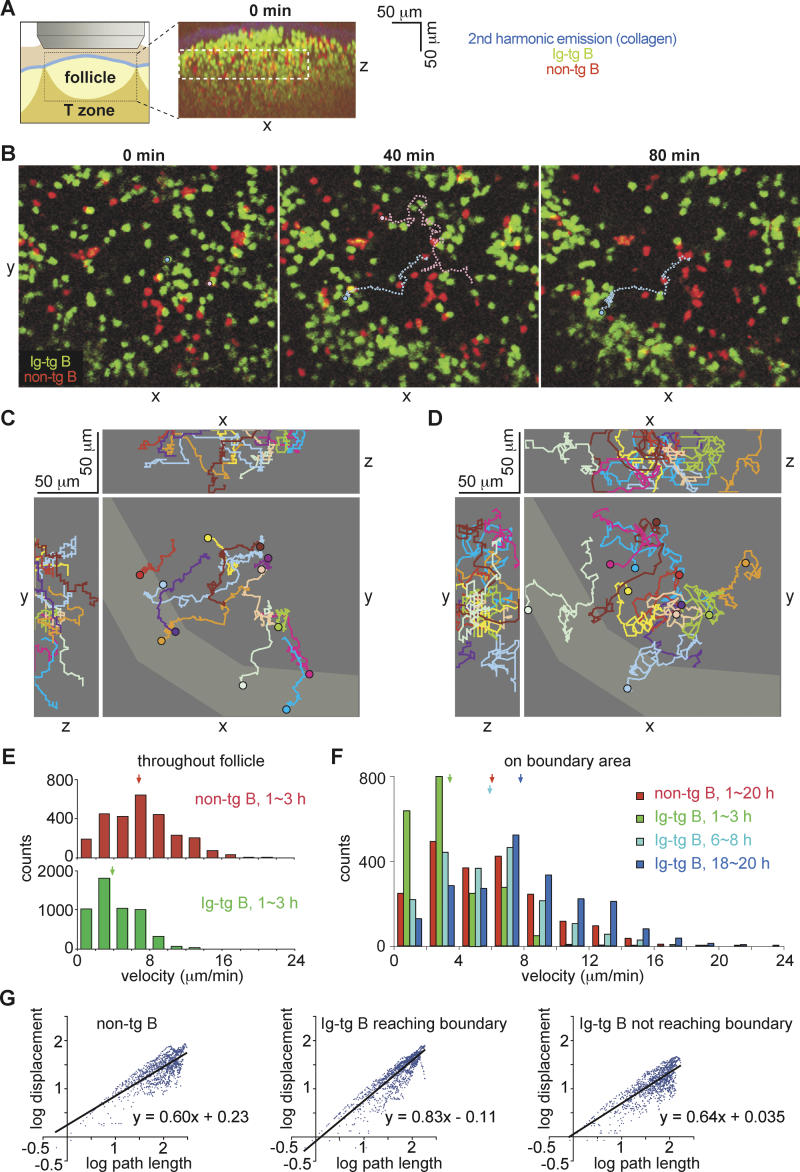
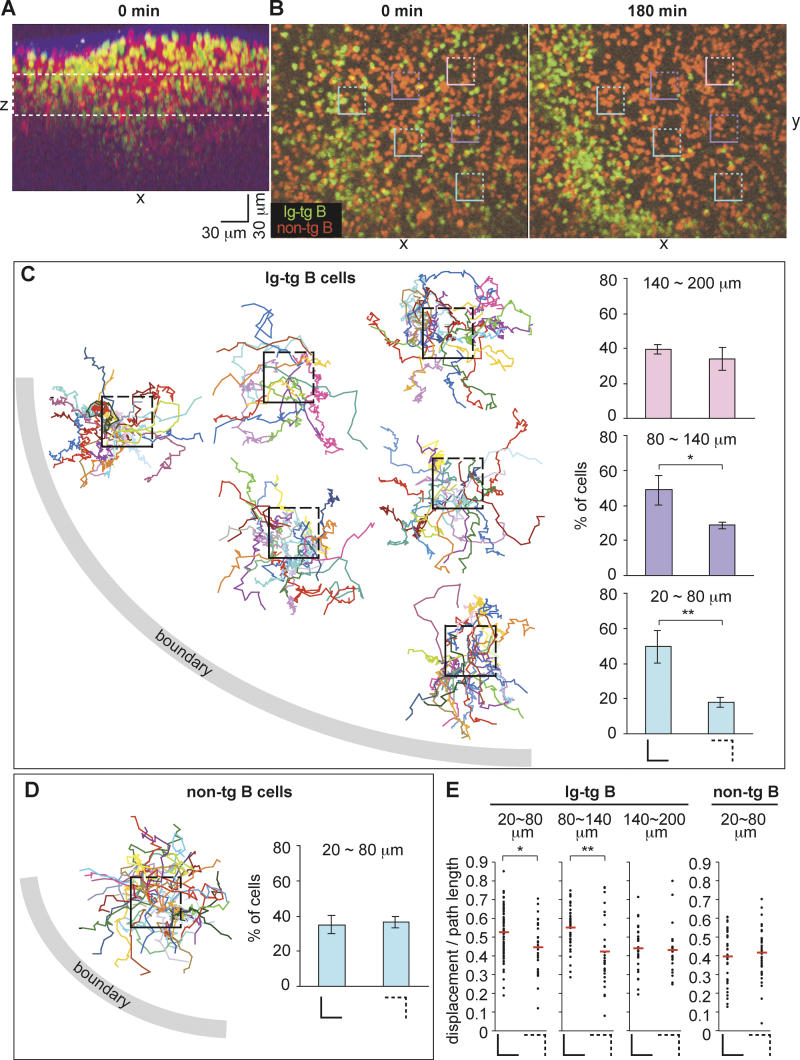
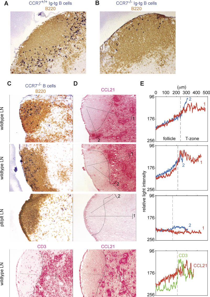
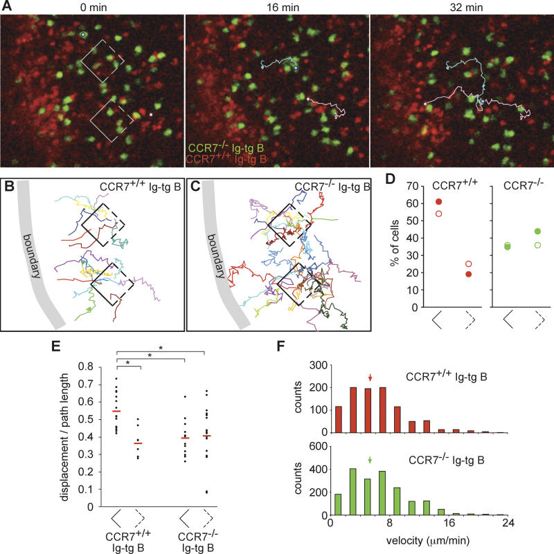
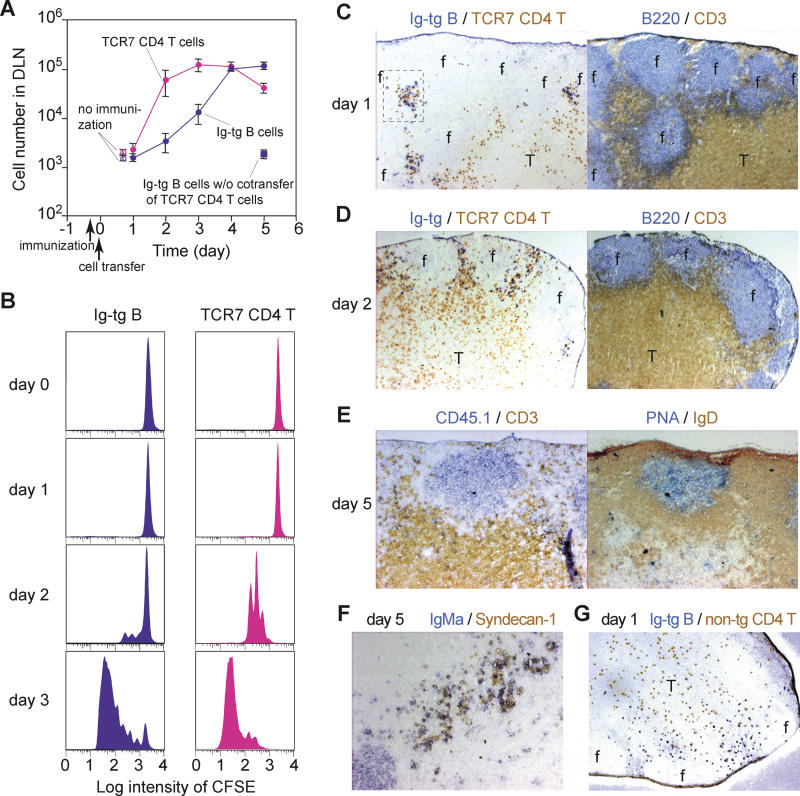
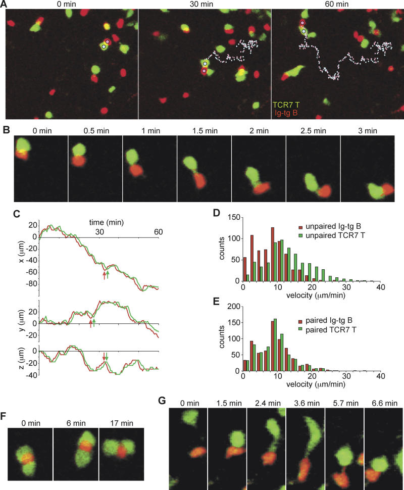
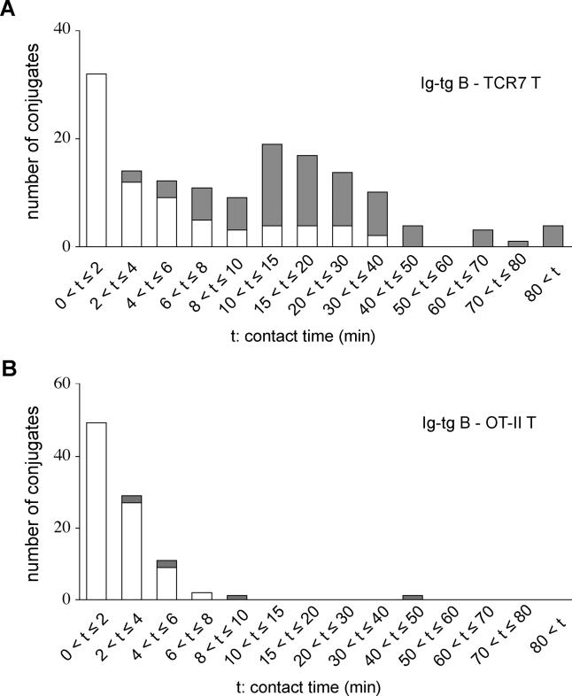
Interactions between B and T cells are essential for most antibody responses, but the dynamics of these interactions are poorly understood. By two-photon microscopy of intact lymph nodes, we show that upon exposure to antigen, B cells migrate with directional preference toward the B-zone-T-zone boundary in a CCR7-dependent manner, through a region that exhibits a CCR7-ligand gradient. Initially the B cells show reduced motility, but after 1 d, motility is increased to approximately 9 microm/min. Antigen-engaged B cells pair with antigen-specific helper T cells for 10 to more than 60 min, whereas non-antigen-specific interactions last less than 10 min. B cell-T cell conjugates are highly dynamic and migrate extensively, being led by B cells. B cells occasionally contact more than one T cell, whereas T cells are strictly monogamous in their interactions. These findings provide evidence of lymphocyte chemotaxis in vivo, and they begin to define the spatiotemporal cellular dynamics associated with T cell-dependent antibody responses.


Figures

Figure 1
Figure 1. Antigen-Engaged B Cells Reduce Random Motility and Migrate Toward the Follicle–T Zone Boundary
(A) On the left is a diagram showing the region of the inguinal lymph node that was imaged. The right panel shows the xz projection view of an image stack collected immediately prior to time-lapse imaging, demonstrating the location of a B cell follicle containing transferred B cells (green and red). The collagen-rich lymph node capsule is visualized by second harmonic emission (blue). The dashed white rectangle shows the region used in the time-lapse image analysis. (B) Time-lapse images of HEL-engaged Ig-tg B cells (green) clustering at the follicle–T zone boundary and naive non-tg B cells (red) in the follicle. The 0-min image is approximately 1 h after antigen exposure (see Video S1). The pathways of an Ig-tg B cell (light blue circle and dotted line) and a non-tg B cell (pink circle and dotted line) are traced as examples. The traced non-tg B cell moved out of the imaging stack at the 57.5-min timepoint. Scale as in (C). (C and D) Tracks of antigen-engaged Ig-tg (C) and naive non-tg (D) B cells in the xy-, xz-, and yz-planes. The boundary as defined by the area of Ig-tg B cell accumulation at 120 min is shown in lighter gray. Tracks cover 30 to 112 min (C) and 30 to 57 min (D). Circles indicate the end point of tracking. (E) Velocity distribution for naive (upper histogram) and antigen-engaged (lower histogram) B cells. Data are shown for 44 Ig-tg cells and 31 non-tg cells. Medians are indicated by arrows. (F) Velocity distributions for non-tg B cells at 1–20 h (red, n = 25) or Ig-tg B cells at 1–3 h (green, n = 29), 6–8 h (light blue, n = 21), or 18–20 h (dark blue, n = 39) after antigen injection. The data are for cells imaged in the boundary regions. Medians are indicated by arrows. (G) Ratios of log (displacement) to log (path length) of naive B cells (20 cells), antigen-engaged B cells that moved to the boundary (22 cells), or antigen-engaged B cells that did not move to the boundary (22 cells). Points indicate data for individual cells collected at cumulative 30-sec time intervals. The formula for each regression line is indicated. The correlation coefficients, R 2, were 0.63, 0.80, and 0.67, respectively. Data are from three experiments and are representative of 12 to ∼18 cells from each recording.
Figure 2
Figure 2. Relationship between Directionality of Ag-Engaged B Cell Migration and Distance from the Follicular Boundary
(A) The xz projection view of an image stack collected immediately prior to time-lapse imaging, demonstrating the location of the B cell follicle containing transferred B cells (green and red). The collagen-rich lymph node capsule is visualized by second harmonic emission (blue). The dashed white rectangle shows the region used in the time-lapse image analysis. (B) Time-lapse images of HEL-engaged Ig-tg B cells (green) clustering at the follicle–T zone boundary and naive non-tg B cells (red) in the follicle. The 0-min image is approximately 1 h after antigen exposure (see Video S2). Square boxes indicate regions used for directionality analysis, shown in (C). Scale bar is as shown in (A). (C) Tracks of antigen-engaged B cells originating from 30-μm follicular cubes. The centers of the boxes are placed proportionally to the actual positions of the boxes shown in (A), with each box corresponding to a 30 μm × 30 μm × 30 μm cube. Tracks cover 8 to 95 min. The histograms show the percentage of cells that moved across the sides of the square (solid lines) that face the boundary (left histograms) and the percentage of cells that moved across the opposite sides (dashed lines) of the squares (right histograms). The bottom, middle, and top histograms show the results with cubes that are 20–80, 80–140, and 140–200 μm away, respectively, from the boundary. Data shown in the histograms are pooled from three experiments. *, p < 0.05; **, p < 0.01. (D) Tracks of naive B cells originating from inside of the middle blue box shown in (A). Tracks cover 5 to 25 min. The histogram shows the percentage of cells that moved across the solid or dashed sides of cubes that are 20–80 μm away from the boundary. Data shown in the histogram are from three experiments. (E) The dot plots show ratios of the displacement to the path length of 8-min tracks of antigen-engaged B cells (left three graphs) or naive B cells (far right graph) originating from the cubes described in (B–D). The distances from the cubes to the boundary are indicated above the graphs. The left and right plots in each graph are the data of tracks that cross the solid and dashed sides of the cubes, respectively. All (100%) of Ig-tg B cells and 94% of non-tg B cells that crossed the sides of the cubes could be tracked for 8 min. The means of each data group are shown as red bars. *, p < 0.05; **, p < 0.01.
Figure 3
Figure 3. CCL21 Concentration Gradients in B Cell Follicles in Lymph Nodes
(A and B) Lymph node sections of wild-type mice that received CCR7+/+ Ig-tg (A) or CCR7−/− Ig-tg B cells (B) and 1 mg of HEL intravenously for 6 h, stained to detect all B cells (brown) and HEL-binding B cells (blue). (C) B cell (upper three panels) or T cell (lower panel) staining of lymph node sections from wild-type and plt/plt mice as indicated. The wild-type lymph nodes shown in the upper panels were from Igha mice that had received CCR7−/− Ighb B cells 1 d before. Staining was to detect all B cells (B220, brown) and transferred CCR7−/− B cells of the Ighb allotype (dark blue) or T cells (CD3, red) as indicated. (D and E) Detection of CCL21 concentration gradients in follicle. In (D), adjacent sections were stained for CCL21. The dashed lines indicate the B/T boundary determined by the distribution of B220 staining. The pixel intensity at each position along the filled line extending from the follicle into the deep T zone (line 1) or the interfollicular T zone (line 2) was averaged across 50 μm perpendicular to the line (the width shown by the bar at the T zone end of each line) and plotted against distance from the follicular end of the line (E) in red for line 1 and blue for line 2. As a negative control, the pixel intensity was determined along a line located in the equivalent location in a CD3-stained section (bottom panel of [C] and shown as a green line in [E]). Pixel intensity was measured using Metamorph software after converting colored pixels to gray scale. A decrease in transmitted light intensity indicates an increase in CCL21. Data are representative of more than five lymph nodes from two mice of each type.
Figure 4
Figure 4. Antigen-Engaged CCR7−/− B Cells Fail to Show Directional Migration toward the Follicle–T Zone Boundary
(A) Time-lapse images of HEL-engaged CCR7−/− (green) and CCR7+/+ (red) Ig-tg B cells in an inguinal lymph node. The 0-min image is ~3.5 h after antigen exposure (see Video S4). Square boxes indicate regions used for directionality analysis, shown in (B). A CCR7−/− Ig-tg B cell (light blue circle and line) and a CCR7+/+ Ig-tg B cell (pink circle and line) are traced as examples. (B and C) Tracks of antigen-engaged CCR7+/+ (B) and CCR7−/− (C) Ig-tg B cells originating from 30-μm follicular cubes, analyzed as described in Figure 2. Tracks cover 3–17 min for CCR7+/+ cells and 3–22 min for CCR7−/− cells. (D) Dot plot showing the percentage of cells that moved across the solid or dashed sides of the cubes. Filled symbols correspond to the data shown in (A–C) and Video S4, open symbols correspond to data obtained in a second time-lapse movie collected 2.5–3.5 h after antigen injection. The cubes were located approximately 20–80 μm from the site of accumulation of CCR7+/+ Ig-tg B cells. (E) The dot plots show ratios of the displacement to the path length of 8-min tracks of antigen-engaged CCR7+/+ or CCR7−/− Ig-tg B cells originating from the cubes described in (A–D). The left and right plots for each cell graph are the data of tracks that cross the solid and dashed sides of the cubes, respectively. A total of 74% of wild-type B cells and 81% of CCR7−/− B cells that crossed the sides of the cubes could be tracked for 8 min. The means of each data group are shown as red bars. *, p < 0.01. (F) Velocity distribution data for CCR7−/− Ig-tg B cells (green, n = 27) and CCR7+/+ Ig-tg B cells (red, n = 40) tracked 2.5–4.2 h after antigen injection. The data are pooled from two time-lapse movies. Medians are indicated by arrows.
Figure 5
Figure 5. Kinetics of HEL-Specific B Cell Expansion and Differentiation in the Presence of HEL-Specific TCR-Transgenic Helper T Cells
(A) Numbers of Ig-tg B cells and TCR7 CD4+ T cells in draining (two inguinal) lymph nodes plotted against time after cell transfer. Shown are means ± standard errors of more than three experiments. Immunization of recipient mice with HEL in adjuvant was done 8 h before cell transfer. (B) Time course of B and T cell division in draining lymph nodes, determined by CFSE dilution. (C–F) Immunohistochemical analysis of draining lymph nodes at days 1–5 following immunization, stained as indicated. Note redistribution of B cells into interfollicular clusters in the presence of helper T cells. An enlarged version of the boxed region in (C) is shown in Figure S2. (G) Distribution of Ig-tg B cells at day 1 in the absence of helper T cells, stained as indicated. Objective magnification in (C), (D), and (G), 5×, and in (E) and (F), 10×.
Figure 6
Figure 6. Dynamics of Antigen-Engaged B Cell–Helper T Cell Interactions
(A) Time-lapse images of Ig-tg B cells interacting with TCR7 CD4+ T cells ~30 h after immunization with HEL in adjuvant, showing T cells moving along behind B cells. The pathways of a B cell (pink dotted line) and a T cell (blue dotted line) remaining bound to each other for more than 1 h are shown (see also Video S5). (B) Time-lapse images showing the dynamics of a B-T conjugate. (C) The t-x, t-y, t-z plots of the interacting B (red line) and T (green line) cells traced in (A). Note the B cell makes turns before the T cell (arrows). (D and E) Velocity measurements of unpaired (D) and paired (E) B and T cells, showing that paired T cells slow to the velocity of the B cell. Velocity data are from 16 cells of each type. (F) Time-lapse images of a B cell interacting with two T cells. (G) Time-lapse images showing an encounter of a B cell and a T cell to form a conjugate.
Figure 7
Figure 7. Contact Times of Antigen-Engaged B cell–Helper T Cell Conjugates
(A) The histogram shows contact time distribution for Ig-tg B cells and TCR7 CD4+ T cells 30 to 50 h after immunization with antigen with adjuvant. Open bars show conjugates that were tracked for the duration of contact and shaded bars show conjugates that could not be tracked for the entire period of contact because the cells entered the field as a conjugate, left the field as a conjugate, or both. (B) Contact time distribution for Ig-tg B cells and OT-II CD4+ T cells 1 to 2 d after antigen priming. Open and shaded bars as in (A).

References

    1. MacLennan IC, Gulbranson-Judge A, Toellner KM, Casamayor-Palleja M, Chan E, et al. The changing preference of T and B cells for partners as T-dependent antibody responses develop. Immunol Rev. 1997;156:53–66. - PubMed
    1. Mills DM, Cambier JC. B lymphocyte activation during cognate interactions with CD4+ T lymphocytes: Molecular dynamics and immunologic consequences. Semin Immunol. 2003;15:325–329. - PubMed
    1. Cyster JG. Chemokines and cell migration in secondary lymphoid organs. Science. 1999;286:2098–2102. - PubMed
    1. Liu YJ, Zhang J, Lane PJ, Chan EY, MacLennan IC. Sites of specific B cell activation in primary and secondary responses to T cell-dependent and T cell-independent antigens. Eur J Immunol. 1991;21:2951–2962. - PubMed
    1. Cyster JG. Signaling thresholds and interclonal competition in preimmune B-cell selection. Immunol Rev. 1997;156:87–101. - PubMed

Publication types

MeSH terms