. 2005 Jun 21;102(25):8860-4.
doi: 10.1073/pnas.0500409102. Epub 2005 Jun 13.

Arranging matter by magnetic nanoparticle assemblers

Affiliations

Arranging matter by magnetic nanoparticle assemblers

Benjamin B Yellen et al. Proc Natl Acad Sci U S A. .

Abstract

We introduce a method for transporting colloidal particles, large molecules, cells, and other materials across surfaces and for assembling them into highly regular patterns. In this method, nonmagnetic materials are manipulated by a fluid dispersion of magnetic nanoparticles. Manipulation of materials is guided by a program of magnetic information stored in a substrate. Dynamic control over the motion of nonmagnetic particles can be achieved by reprogramming the substrate magnetization on the fly. The unexpectedly large degree of control over particle motion can be used to manipulate large ensembles of particles in parallel, potentially with local control over particle trajectory.


Figures

Fig. 1.
Fig. 1.
Bead levitation and microtweezing by magnetic traps. In the absence of external magnetic field, latex beads (red spheres) are stably levitated above the surface as illustrated in a due to repulsion by the magnetic nanoparticles in the fluid (brown dots). When the external field is activated, the particles are attracted to different positions on the traps, depending on the orientation of the field (blue arrow) with respect to trap magnetization (white arrow). The bead is initially attracted to the left end of the trap in c, and after successive magnetic field rotations, the bead moves from the left end to on top of the trap, then to the right end of the trap, and finally in between traps. In c, a quasi-static transport model for bead movement in rotating magnetic field is demonstrated. Provided in b is experimental demonstration of 3-μm latex beads (Duke Scientific) assembling onto 5-μm magnetic traps in the influence of static applied magnetic field. (Scale bar: 25 μm.)
Fig. 2.
Fig. 2.
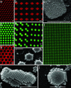
Assembly as a function of particle to trap size ratio. The assembly of micrometer- and submicrometer-sized beads onto magnetic traps of various shapes is demonstrated. The bead sizes in each of the images are as follows: 3 μm(a), 2 μm(b and g), 90 nm (c), 5 μm(df), 1 μm(h), and 500 nm (i and j). The beads assemble onto 5-μm circular magnetic traps in a, b, d, f, h, and j, whereas images c, e, and i show the assembly of beads onto rectangular magnetic traps with 3 × 12-μm planar dimensions. Image g shows beads assembling onto the inverse magnetic pattern (i.e., 5-μm circular holes in a sheet of magnetic material). Images b, c, and gj were taken after the fluid had evaporated, and images a and df were taken while still inside the fluid. It is curious that with submicrometer-sized beads sometimes hexagonal packing and other times fcc packing was observed. (Scale bars: 5 μm.)
Fig. 3.
Fig. 3.
Bead transport under fields rotating out-of-plane. The sequence of optical images taken from video footage demonstrates how a single 7-μm bead will follow a programmable route across a small section of magnetic traps, depending on the axis of field rotation and trap magnetization. The bead begins in the lower left corner of the surface. It moves initially toward the upper left corner under the influence of rotating magnetic field. When it reaches the upper left corner, the bead makes a right turn in response to a joint shift in the axis of magnetic field rotation and trap magnetization by a 90° angle. The bead then continues forward on its new path toward the upper right corner of the array. (Scale bar: 25 μm.)
Fig. 4.
Fig. 4.
Bead motion as a function of frequency and magnetic nanoparticle concentration. Depicted is the motion of 3-μm beads inside ferrofluid solutions of concentrations 0.11%, 0.27%, and 0.55% solids (vol). The maximum rate of bead motion is highest for ferrofluid of 0.55% concentration, followed by 0.27% and then 0.11% concentration. The error bars signify the range of velocities for each frequency taken from the standard deviation in velocity for each data set.
Fig. 5.
Fig. 5.
Bead motion as a function of magnetization patterns. Shown is the movement of 3-μm beads when the axis of magnetic field rotation is aligned perpendicularly to the substrate normal. Depending on the underlying magnetic trap pattern, the beads are concentrated in the left region, but are allowed to freely pass through the right region. The pattern in the left region consists of an array of 5-μm circular magnetic traps separated by 3 μm in a hexagonal formation. The pattern in the right region consists of an array of 3 × 8-μm rectangular magnetic traps spaced with 5 μm of separation in a rectangular grid. The line of bead motion is parallel to the minor axis of the rectangular traps in the right region. (Scale bar: 50 μm.)

References

    1. Dufresne, E. R. & Grier, D. G. (1998) Rev. Sci. Instrum. 69, 1974–1977.
    1. Curtis, J. E., Koss, B. A. & Grier, D. G. (2002) Opt. Comm. 207, 169–175.
    1. Velev, O. D., Prevo, B. G. & Bhatt, K. H. (2003) Nature 426, 515–516. - PubMed
    1. Suo, Z. & Hong, W. (2004) Proc. Natl. Acad. Sci. USA 101, 7874–7879. - PMC - PubMed
    1. Ozin, G. A. & Yang, S. M. (2001) Adv. Funct. Mater. 11, 95–104.

LinkOut - more resources