. 2005 Sep;11(9):1430-40.
doi: 10.1261/rna.7206305. Epub 2005 Jul 25.

A mutational analysis of U12-dependent splice site dinucleotides

Affiliations

A mutational analysis of U12-dependent splice site dinucleotides

Rosemary C Dietrich et al. RNA. 2005 Sep.

Abstract

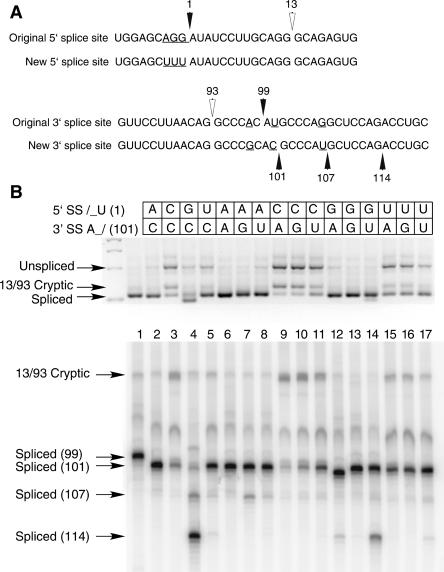
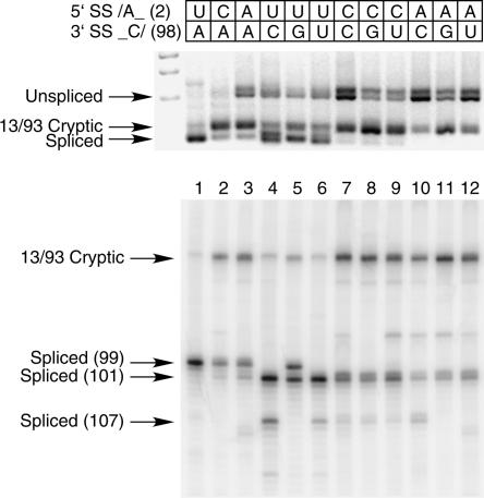
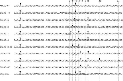
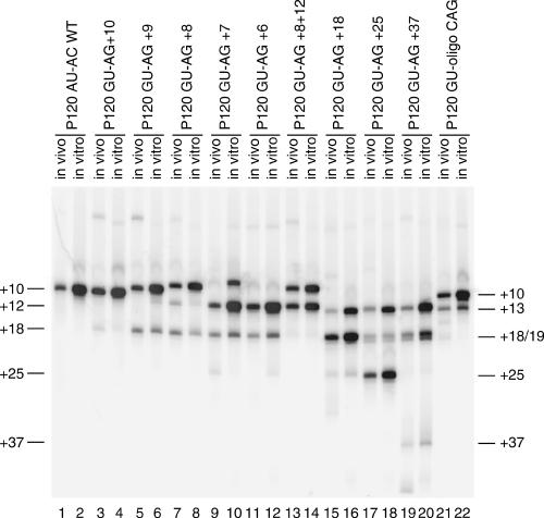
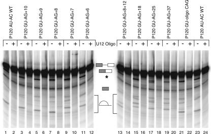
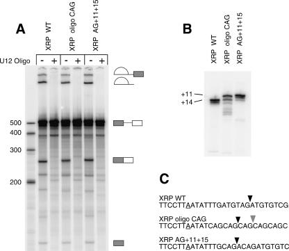
Introns spliced by the U12-dependent minor spliceosome are divided into two classes based on their splice site dinucleotides. The /AU-AC/ class accounts for about one-third of U12-dependent introns in humans, while the /GU-AG/ class accounts for the other two-thirds. We have investigated the in vivo and in vitro splicing phenotypes of mutations in these dinucleotide sequences. A 5' A residue can splice to any 3' residue, although C is preferred. A 5' G residue can splice to 3' G or U residues with a preference for G. Little or no splicing was observed to 3' A or C residues. A 5' U or C residue is highly deleterious for U12-dependent splicing, although some combinations, notably 5' U to 3' U produced detectable spliced products. The dependence of 3' splice site activity on the identity of the 5' residue provides evidence for communication between the first and last nucleotides of the intron. Most mutants in the second position of the 5' splice site and the next to last position of the 3' splice site were defective for splicing. Double mutants of these residues showed no evidence of communication between these nucleotides. Varying the distance between the branch site and the 3' splice site dinucleotide in the /GU-AG/ class showed that a somewhat larger range of distances was functional than for the /AU-AC/ class. The optimum branch site to 3' splice site distance of 11-12 nucleotides appears to be the same for both classes.


Figures

FIGURE 1.
FIGURE 1.
(A) Comparison of the 5′ and 3′ splice site regions of human P120 intron F used for the terminal nucleotide mutant analysis. The top lines show the wild-type genomic sequence and the bottom lines show the sequences used as the starting point for the mutants. The changes were designed to reduce the use of nearby cryptic splice sites and to optimize the branch site to 3′ splice site distance. (B) Pattern of in vivo splicing of the original wild type (lane 1), the new wild type (lane 2), and the 15 possible mutants of the terminal nucleotides as indicated by the key at the top. The indicated minigene constructs were transfected into CHO cells and total RNA prepared after 48 h. The splicing pattern of the P120 intron F was determined by RT-PCR amplification and separation of the products on an agarose gel (top) and a denaturing polyacrylamide gel (bottom). The positions of spliced and unspliced PCR products are shown as well as the position of the U2-dependent 13/93 cryptic splice that is activated in some constructs. The numbers at the left indicate the position of the 3′ splice site. In all cases, except for the 13/93 product, the U12-dependent 5′ splice site at position 1 was used.
FIGURE 2.
FIGURE 2.
In vivo splicing of mutants in the 5′ splice site +2U and 3′ splice site −2A positions. The mutants were constructed in the original P120 wild type shown in Figure 1A (top). Correctly spliced RNA uses the 3′ splice site at 99. Shown are the original wild type (lane 1), two single mutants of the 5′ splice site +2 position (lanes 2,3), three single mutants of the 3′ splice site −2 position (lanes 46), and six double mutants (lanes 712). The indicated minigene constructs were transfected into CHO cells and total RNA prepared after 48 h. The splicing pattern of the P120 intron F was determined by RTPCR amplification and separation of the products on an agarose gel shown at the top and a denaturing polyacrylamide gel at the bottom. The positions of spliced and unspliced PCR products are shown as well as the position of the U2-dependent 13/93 cryptic splice that is activated in some constructs. The numbers at the left indicate the position of the 3′ splice site. In all cases, except for the 13/93 product, the U12-dependent 5′ splice site at position 1 was used.
FIGURE 3.
FIGURE 3.
Sequences of the 3′ splice site mutants used to determine the branch site to 3′ splice site spacing constraints for a /GU-AG/ U12-dependent intron. The top line is the original P120 intron F sequence with the consensus 5′ splice site and branch site sequences boxed. The second line is the /GU-AG/ version of this intron, which includes a mutation of the −1G to an A adjacent to the 5′ splice site. This reduces the use of this 5′ splice site by the U2-dependent spliceosome (Dietrich et al. 1997). The 3′ splice sites of the constructs are shown at the right of the figure. The common branch site is shown in bold and the mutated positions are underlined. The sites of in vivo splicing for each construct are indicated by the arrows. Major sites are indicated by dark arrowheads and minor sites are indicated by light arrowheads. The numbers at the top refer to the distance in nucleotides between the branch site adenosine and the dashed lines.
FIGURE 4.
FIGURE 4.
Patterns of in vivo and in vitro splicing of 3′ splice site spacing mutants. The indicated minigene constructs were either transfected into CHO cells and total RNA prepared after 48 h or transcribed in vitro and subjected to splicing under U12-dependent conditions in HeLa cell nuclear extract (see Fig. 5). The splicing patterns of the P120 intron F in both the in vivo and in vitro RNA samples were determined by RT-PCR amplification and separation of the products on a denaturing polyacrylamide gel. The numbers at the left indicate the distance in nucleotides between the branch site and the 3′ splice site in each product. The results are summarized in Figure 3. In all cases, the U12-dependent 5′ splice site at position 1 was used.
FIGURE 5.
FIGURE 5.
In vitro splicing patterns of P120 3′ splice site spacing mutants. Templates for in vitro transcription of the indicated 3′ splice site constructs were produced by PCR amplification from the indicated minigene constructs. Equal amounts of transcribed precursor RNAs were spliced in vitro. All reactions contained an anti-U2 snRNA 2′-O-methyl oligonucleotide that inhibits U2-dependent splicing. An anti-U12 snRNA 2′-O-methyl oligonucleotide was also added to even numbered lanes to inhibit U12-dependent splicing. The structures of the various RNA products are shown in the middle and correspond, from top to bottom, to the unspliced precursor, spliced exon product, the exon 1 intermediate generated by the first step of splicing, and the excised lariat intron generated by the second step of splicing. The lariat introns from different constructs migrate differently due to the varying length of RNA 3′ of the branch. A degradation product that migrates below the position of spliced exons is labeled with an asterisk.
FIGURE 6.
FIGURE 6.
In vitro splicing patterns of XRP 3′ splice site spacing mutants. Templates for in vitro transcription were produced by PCR amplification from the XRP construct described by McConnell et al. (2002). Equal amounts of transcribed precursor RNAs were spliced in vitro. All reactions contained an anti-U2 snRNA 2′-O-methyl oligonucleotide that inhibits U2-dependent splicing. An anti-U12 snRNA 2′-O-methyl oligonucleotide was also added to even numbered lanes to inhibit U12-dependent splicing. (A) Products of in vitro splicing reactions run on a denaturing polyacrylamide gel. The bands corresponding to the precursor RNA and the intermediates and products of splicing are diagramed. (B) RT-PCR amplification of the spliced products from the reactions in A were run on a denaturing polyacrylamide gel. (C) The sequences of the branch and 3′ splice site regions of the wild-type and mutant XRP constructs are shown. The major sites of splicing are marked with black arrowheads; minor sites are marked with gray arrowheads.

References

    1. Aebi, M., Hornig, H., Padgett, R.A., Reiser, J., and Weissmann, C. 1986. Sequence requirements for splicing of higher eukaryotic nuclear pre-mRNA. Cell 47: 555–565. - PubMed
    1. Burge, C.B. and Sharp, P.A. 1997. Classification of introns: U2-type or U12-type. Cell 91: 875–879. - PubMed
    1. Burge, C.B., Tuschl, T., and Sharp, P.A. 1999. Splicing of precursors to mRNAs by the spliceosome. In The RNA world, 2d ed. (eds. R.F. Gestland et al.), pp. 525–560. Cold Spring Harbor Laboratory Press, Cold Spring Harbor, NY.
    1. Chanfreau, G. and Jacquier, A. 1993. Interactions of intronic boundaries is required for the second splicing step efficiency of a group II intron. EMBO J. 12: 5173–5180. - PMC - PubMed
    1. Chanfreau, G., Legrain, P., Dujon, B., and Jacquier, A. 1994. Interaction between the first and last nucleotides of pre-mRNA introns is a determinant of 3′ splice site selection in S. cerevisiae. Nucleic Acids Res. 22: 1981–1987. - PMC - PubMed

Publication types

LinkOut - more resources