

Tissue-plastinated vs. celloidin-embedded large serial sections in video, analog and digital photographic on-screen reproduction: a preliminary step to exact virtual 3D modelling, exemplified in the normal midface and cleft-lip and palate
- PMID: 16050904
- PMCID: PMC1571518
- DOI: 10.1111/j.1469-7580.2005.00438.x
Tissue-plastinated vs. celloidin-embedded large serial sections in video, analog and digital photographic on-screen reproduction: a preliminary step to exact virtual 3D modelling, exemplified in the normal midface and cleft-lip and palate
Abstract
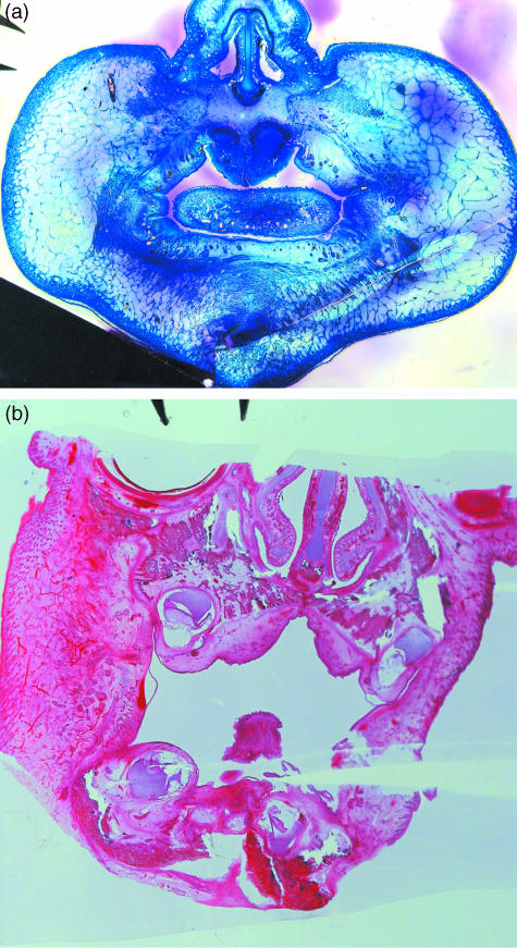
This study analyses tissue-plastinated vs. celloidin-embedded large serial sections, their inherent artefacts and aptitude with common video, analog or digital photographic on-screen reproduction. Subsequent virtual 3D microanatomical reconstruction will increase our knowledge of normal and pathological microanatomy for cleft-lip-palate (clp) reconstructive surgery. Of 18 fetal (six clp, 12 control) specimens, six randomized specimens (two clp) were BiodurE12-plastinated, sawn, burnished 90 microm thick transversely (five) or frontally (one), stained with azureII/methylene blue, and counterstained with basic-fuchsin (TP-AMF). Twelve remaining specimens (four clp) were celloidin-embedded, microtome-sectioned 75 microm thick transversely (ten) or frontally (two), and stained with haematoxylin-eosin (CE-HE). Computed-planimetry gauged artefacts, structure differentiation was compared with light microscopy on video, analog and digital photography. Total artefact was 0.9% (TP-AMF) and 2.1% (CE-HE); TP-AMF showed higher colour contrast, gamut and luminance, and CE-HE more red contrast, saturation and hue (P < 0.4). All (100%) structures of interest were light microscopically discerned, 83% on video, 76% on analog photography and 98% in digital photography. Computed image analysis assessed the greatest colour contrast, gamut, luminance and saturation on video; the most detailed, colour-balanced and sharpest images were obtained with digital photography (P < 0.02). TP-AMF retained spatial oversight, covered the entire area of interest and should be combined in different specimens with CE-HE which enables more refined muscle fibre reproduction. Digital photography is preferred for on-screen analysis.
Figures


Similar articles
-
Evaluation of two 3D virtual computer reconstructions for comparison of cleft lip and palate to normal fetal microanatomy.Anat Rec A Discov Mol Cell Evol Biol. 2006 Mar;288(3):248-62. doi: 10.1002/ar.a.20289. Anat Rec A Discov Mol Cell Evol Biol. 2006. PMID: 16456872
-
Relative contributions of the nasal septum and airways to total nasal capsule volume in normal and cleft lip and palate fetal specimens.Cleft Palate J. 1988 Jul;25(3):282-7. Cleft Palate J. 1988. PMID: 3168271
-
Size and growth rate of the tongue in normal and cleft lip and palate human fetal specimens.Cleft Palate Craniofac J. 1991 Apr;28(2):212-6. doi: 10.1597/1545-1569_1991_028_0212_sagrot_2.3.co_2. Cleft Palate Craniofac J. 1991. PMID: 2069978
-
Development of the orbicularis oris muscle in normal and cleft lip and palate human fetuses using three-dimensional computer reconstruction.Plast Reconstr Surg. 1988 Mar;81(3):336-45. doi: 10.1097/00006534-198803000-00004. Plast Reconstr Surg. 1988. PMID: 3277211 Review.
-
[Experimental considerations of the mechanism of lip and palate fusion].Minerva Stomatol. 1994 Dec;43(12):577-83. Minerva Stomatol. 1994. PMID: 7739492 Review. Italian.
References
-
- Aritan S, Dabnichki P, Bartlett R. Program for generation of three-dimensional finite element mesh from magnetic resonance imaging scans of human limbs. Med Eng Phys. 1997;19:681–689. - PubMed
-
- Atkins RW, Byrd HS, Tebbetts JB. Some observations relative to the levator veli palatini muscles in the cleft palate. Cleft Palate J. 1982;19:267–269. - PubMed
-
- Azzam NA, Kuehn DP. The morphology of musculus uvulae. Cleft Palate J. 1977;14:78–87. - PubMed
-
- Boorman JG, Sommerlad BC. Musculus uvulae and levator palati: their anatomical and functional relationship in velopharyngeal closure. Br J Plast Surg. 1985;38:333–338. - PubMed
-
- Brescia NJ. Anatomy of the lip and palate. In: Grabb WC, Reserstein SW, Bzock UR, editors. Cleft Lip and Palate. Boston: Little, Brown; 1971. pp. 13–20.
Publication types
MeSH terms
Substances
LinkOut - more resources
Full Text Sources
Medical
Miscellaneous
