An ankle-foot orthosis powered by artificial pneumatic muscles
- PMID: 16082019
- PMCID: PMC1351122
- DOI: 10.1123/jab.21.2.189
An ankle-foot orthosis powered by artificial pneumatic muscles
Abstract
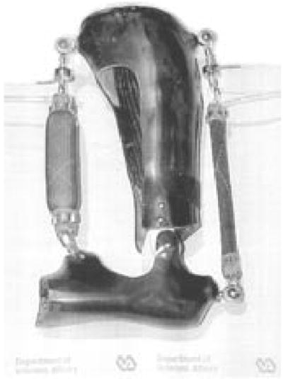
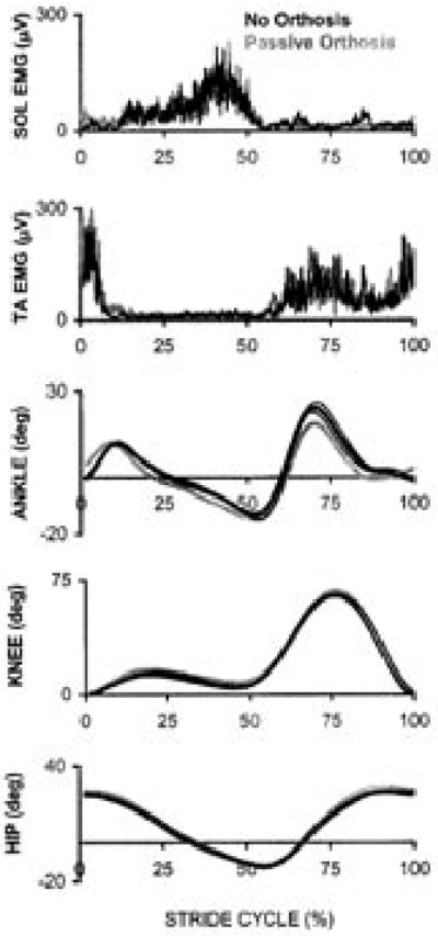
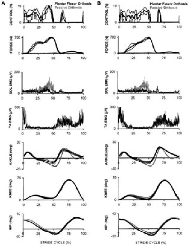
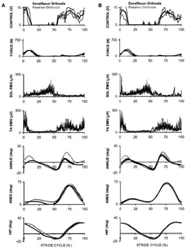
We developed a pneumatically powered orthosis for the human ankle joint. The orthosis consisted of a carbon fiber shell, hinge joint, and two artificial pneumatic muscles. One artificial pneumatic muscle provided plantar flexion torque and the second one provided dorsiflexion torque. Computer software adjusted air pressure in each artificial muscle independently so that artificial muscle force was proportional to rectified low-pass-filtered electromyography (EMG) amplitude (i.e., proportional myoelectric control). Tibialis anterior EMG activated the artificial dorsiflexor and soleus EMG activated the artificial plantar flexor. We collected joint kinematic and artificial muscle force data as one healthy participant walked on a treadmill with the orthosis. Peak plantar flexor torque provided by the orthosis was 70 Nm, and peak dorsiflexor torque provided by the orthosis was 38 Nm. The orthosis could be useful for basic science studies on human locomotion or possibly for gait rehabilitation after neurological injury.
Figures
References
-
- Andersen JB, Sinkjaer T. An actuator system for investigating electrophysiological and biomechanical features around the human ankle joint during gait. IEEE Transactions on Rehabilitation Engineering. 1995;3:299–306.
-
- Andersen JB, Sinkjaer T. Mobile ankle and knee perturbator. IEEE Transactions on Bio-medical Engineering. 2003;50:1208–1211. - PubMed
-
- Blaya JA, Herr H. Adaptive control of a variable-impedance ankle-foot orthosis to assist drop-foot gait. IEEE Transactions on Neural Systems and Rehabilitation Engineering. 2004;12:24–31. - PubMed
-
- Davis S, Tsagarakis N, Canderle J, Caldwell DG. Enhanced modelling and performance in braided pneumatic muscle actuators. International Journal of Robotics Research. 2003;22:213–227.
-
- De Luca CJ. The use of surface electromyography in biomechanics. Journal of Applied Biomechanics. 1997;13:135–163.
Publication types
MeSH terms
Grants and funding
LinkOut - more resources
Full Text Sources
Other Literature Sources