. 2005 Sep;26(8):2067-76.

Imaging manifestations of spinal fractures in ankylosing spondylitis

Affiliations

Imaging manifestations of spinal fractures in ankylosing spondylitis

Yi-Fen Wang et al. AJNR Am J Neuroradiol. 2005 Sep.

Abstract

Background and purpose: Spinal fractures in ankylosing spondylitis (AS) were difficult to diagnose before CT and MR imaging were available. The purpose of our investigation was to characterize spinal fractures and determine the value of different imaging modalities in AS.

Methods: Twelve successive cases of spinal fractures were identified in MR imaging files of AS patients. Conventional radiographs were available for 12, CT scans for 7, and 3D-CT scans for 4. We carefully reviewed clinical histories and imaging presentations.

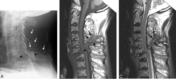
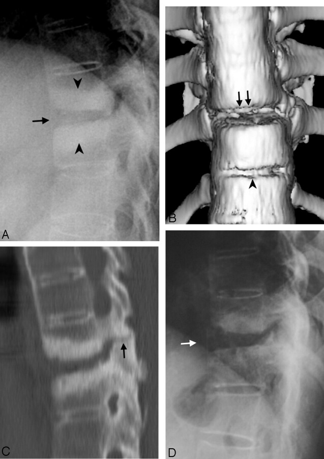
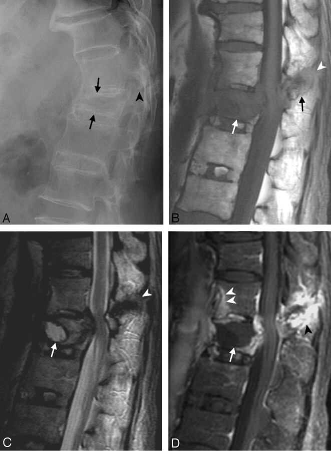
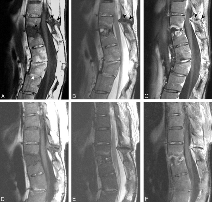
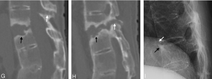
Results: Fractures were found in the cervical spine in 3 patients and in the thoracolumbar spine in 9. The 3 columns of the spine were involved in 11 patients. A routine 4-mm axial CT was not enough to demonstrate all fractures and ligament tears. The sensitivities of 3D-CT scans for demonstration of the following problems were similar to that of MR imaging and were better than that of conventional radiographs: tearing of the posterior longitudinal ligament, the thoracic spinous process fracture, and the facet fracture. MR imaging depicted these following findings that usually were not shown on conventional radiographs or 3D-CT scans: cord deformity, soft tissue disruption, and ligament tears in the posterior column. MR imaging also showed avascular necrosis and occult fractures better than conventional radiographs or CT scans.

Conclusions: MR imaging shows abnormalities in AS that may not be clear or even detectable by using other imaging methods. With the capability to show lesions in the posterior column, MR imaging can serve to evaluate AS patients with spinal fracture for the possibility of 3-column involvement.


Figures

F<sc>ig</sc> 1.
Fig 1.
Case 2. Fracture of the anterior C7 vertebral body and posterior C6 vertebral body with traumatic spondylolisthesis (C6 on C7), tearing of the anterior and posterior longitudinal ligaments. The fracture line extended posteriorly through the C5–C6 facet, to the C3–C5 spinous processes, and involved all 3 spinal columns but at different levels. A, Conventional radiograph of the cervical spine 16 days after trauma, showing ossification of the ALL due to AS. The distance between the posterior border of the C6 vertebral body (black arrowhead) and the spinolaminar line of C6 (black arrow) is increased, which indicates a fracture of the C6 pedicles bilaterally. There are also fractures in C3–C5 spinous processes (white arrows). B, T1-weighted image 29 days after trauma, showing the hypointense ligament tears in the posterior column (white arrow) and in C3–C5 spinous process (black arrows). Discontinuity of the normally dark posterior longitudinal ligament at C6–C7 indicates tearing of this ligament (arrowhead). C, T2-weighted image 29 days after trauma. The ligament tears in the posterior column (white arrow) and the fracture in the spinous process (black arrows) are hypointense. Slight hyperintense dots inside the hypointense area are the displaced spinous processes and fat-containing structures.
F<sc>ig</sc> 2.
Fig 2.
Case 3. Diskovertebral erosion, pseudarthrosis, with posterior column involvement. A, Conventional radiograph of the thoracic spine, showing squaring of the vertebral bodies and ossification of the ALL due to AS. Increased disk space of T10–T11 (arrow), endplate erosion, and hyperostotic change in the bone marrow of the adjacent vertebral bodies (arrowheads) were compatible with pseudarthrosis. The hyperostotic change is consistent with a long-term chronic lesion. The facet lesion is not shown well in the conventional radiographs because of overlapping by adjacent structures. B, Anterior 3D surface-rendered CT reconstruction shows a gap in the ALL and disk space at T10–T11 level (arrows) and another gap in the ALL at the level of the T11–T12 disk (arrowhead), which indicates tearing of the ALL and erosion of the vertebral body at the insertion of this ligament. C, Sagittal, thin-section, reformatted CT scan image. In addition to the above-mentioned lesions, this reformatted image shows the fracture in the facet (arrow). The diskovertebral lesion is shown better in this image than in conventional radiographs. D, Conventional radiograph 30 months earlier than A–C, showing squaring of the vertebral bodies and diskovertebral lesion with less extensive sclerotic change (white arrow) than A.
F<sc>ig</sc> 3.
Fig 3.
Case 9. Imaging studies, 1 month after a fall. This patient had fracture in the L1 vertebral body with avascular necrosis. There was also fracture in the anterior inferior T12 vertebral body. The fracture line extended posteriorly with the involvement of the superior articular process of L1, the inferior articular process, and spinous process of T12. All 3 columns were involved. A, Conventional radiograph, showing ossification of the ALL, and reduced height with wedge deformity of the L1 vertebral body (arrows) and fracture in the facet (arrowhead). B, T1-weighted image, showing a hypointense signal intensity in the L1 vertebral body (white arrow) due to avascular necrosis and edema, fracture of the T12 spinous process (black arrow), and soft tissue disruption and ligament tears in the posterior column (white arrowhead). C, T2-weighted image, showing avascular necrosis with fluid inside the L1 vertebral body (white arrow), edema posterior to the fluid cavity, as well as retropulsion with stenosis of the spinal canal and compression of the cord. The bone fracture, ligament tears in the posterior column, and adjacent soft tissue disruption are hypointense (arrowhead). D, Gadolinium-enhanced T1-weighted image, showing the nonenhancing components of avascular necrosis and edema inside the L1 vertebral body (arrow) with enhancement beyond its border. The fracture in the posterior component is delineated with marginal enhancement (black arrowhead). There is enhancement in the anterior inferior T12 vertebral body (white arrowheads) caused by an occult fracture. The fracture cannot be surely identified in the conventional radiograph (A). It became obvious in the conventional radiograph of the spine taken later (not shown).
F<sc>ig</sc> 4.
Fig 4.
Case 12. A, T1-weighted image. B, T2-weighted image. C, Gadolinium-enhanced T1-weighted image. There are 2 levels of trauma. The upper one is an anterior opening fracture at T11–T12 with disk-space widening containing a fluid cavity inside (A, arrow) forming a pseudarthrosis. Erosion and enhancement is present in the adjacent endplates and vertebral bodies extending from the anterior border to the posterior border at this level. There are fractures in the facets, spinous process, and the interspinous space of T10–T11, with hypointensity on T1-weighted and T2-weighted images (A–C, black arrowheads). The postcontrast T1-weighted image (C) shows enhancement along the margin of the fracture line. The lower level is an anterior wedge deformity of the L2 vertebral body (A, white arrowhead). The L2 vertebral body has no edema, enhancement or cavity inside, and is compatible with an old healed fracture. There is suspicious retrolisthesis of L2 on L3, and L3 on L4. The disk space of L1–L2 and L2–L3 are narrowed, with abnormal signal intensity in the disk space and the adjacent bone marrow from ankylosing spondylitis. D, E and F, MR imaging 14 months later than A–C show little change. G and H, Sagittal reformatted CT scan 14 months after AC in the midline (G) and off midline (H) show the fracture line (arrows) and adjacent bony sclerosis. I, Conventional radiograph 54 months earlier than AC shows possible avulsion injury with a teardrop fragment in the anterior inferior T11 vertebral body (white arrow) and reactive hyperostosis at anterior superior corner of T12 vertebral body as a result of AS called “shiny corner” configuration (black arrow). There is squaring of the vertebral bodies and ossification of the ALL in other levels due to AS.

References

    1. Finkelstein JA, Chapman JR, Mirza S. Occult vertebral fractures in ankylosing spondylitis. Spinal Cord 1999;37:444–447 - PubMed
    1. Lawrence JS. The prevalence of arthritis. Br J Clin Pract 1963;17:699. - PubMed
    1. Hitchon PW, From AM, Brenton MD, et al. Fractures of the thoracolumbar spine complicating ankylosing spondylitis. J Neurosurg 2002;97(2 suppl):218–222 - PubMed
    1. Graham GP, Evans PD. Spinal fractures in patients with ankylosing spondylitis. Injury 1991;22:426–427 - PubMed
    1. Gartman JJ Jr, Bullitt E, Baker ML. Axis fracture in ankylosing spondylitis: case report. Neurosurgery 1991;29:590–593 - PubMed

Publication types

MeSH terms