. 2006 Jan 1;90(1):65-76.
doi: 10.1529/biophysj.105.071480. Epub 2005 Oct 7.

Mechanics and dynamics of actin-driven thin membrane protrusions

Affiliations

Mechanics and dynamics of actin-driven thin membrane protrusions

Erdinç Atilgan et al. Biophys J. .

Abstract

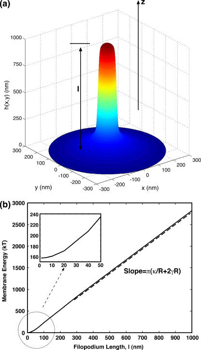
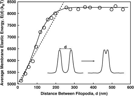
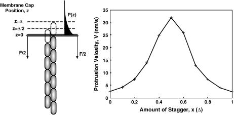
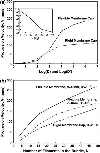
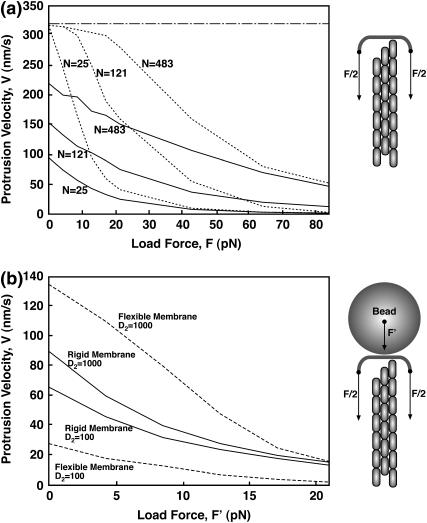
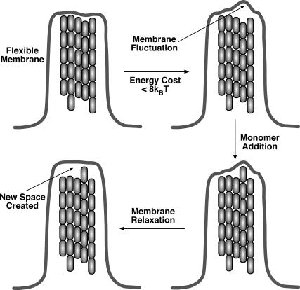
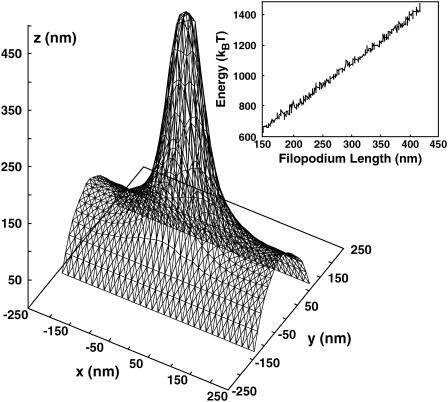
Motile cells explore their surrounding milieu by extending thin dynamic protrusions, or filopodia. The growth of filopodia is driven by actin filament bundles that polymerize underneath the cell membrane. We compute the mechanical and dynamical features of the protrusion growth process by explicitly incorporating the flexible plasma membrane. We find that a critical number of filaments are needed to generate net filopodial growth. Without external influences, the filopodium can extend indefinitely up to the buckling length of the F-actin bundle. Dynamical calculations show that the protrusion speed is enhanced by the thermal fluctuations of the membrane; a filament bundle encased in a flexible membrane grows much faster. The protrusion speed depends directly on the number and spatial arrangement of the filaments in the bundle and whether the filaments are tethered to the membrane. Filopodia also attract each other through distortions of the membrane. Spatially close filopodia will merge to form a larger one. Force-velocity relationships mimicking micromanipulation experiments testing our predictions are computed.


Figures

FIGURE 1
FIGURE 1
Equilibrium membrane energy as a function of the length of the protrusion, l, obtained from minimization of the Helfrich energy. (a) The membrane profile, h(r), is written as a series expansion formula image and then expansion coefficients an varied until the minimum energy is reached. The value r′ = 500 nm is the radius of the outer boundary and h(0) = l, h(r′) = 0. For the particular profile shown, l = 1000 nm. (b) For relatively long protrusions, E is a linear function of l. The slope is given by formula image For shorter protrusions, the energy profile is nonlinear. The inset shows the energy of the membrane for protrusions up to 50 nm.
FIGURE 2
FIGURE 2
The interaction energy between two filopodia as a function of their separation, d. The energy is minimized when the filopodia merge. The interaction range, d0, is approximately twice the diameter of the filopodium; d0 is ≈200 nm. The circles are our computational results and the solid line is a guide to the eye. The dashed line shows the estimated energy using the force estimate of Eq. 6.
FIGURE 3
FIGURE 3
Two possible models for describing filopodium extension. The first model (left) is the standard Brownian ratchet model where a F-actin bundle protrudes against a rigid object under load. The rigid object is the tip of the membrane extension, or cap. The load force on the cap is give by Eq. 4. For this model, the spatial arrangement of the bundle in the x,y-plane is of no importance. However, how the filaments are staggered in the z-direction is important. In the second model (right), a flexible membrane is considered. For the flexible membrane, we find that the geometrical arrangement of the filaments is important. In our computation, we vary the spacing between the filaments, d. The physiological spacing is ∼d = 15 nm. In these models, D is the diffusion constant of the rigid membrane cap and D′ is the diffusion constant of the small membrane elements.
FIGURE 4
FIGURE 4
Model 1: a rigid cap being propelled by an F-actin bundle. The external force, F, is 13 pN, given by Eq. 4. (a) Velocity as a function of the log of the diffusion constant, D, for various number of filaments. (b) The protrusion speed as a function of number of filaments, N, for different values of D.
FIGURE 5
FIGURE 5
For two filaments propelling a rigid object under load, an estimate of the protrusion speed can be obtained in the limit of D → ∞. The steady-state probability distribution can be separated into several regions, each with a protrusion velocity. The total average velocity is a statistical sum of these contributions. The protrusion velocity for two filaments as a function of the stagger spacing, x, is shown on the right. The actin concentration in this case is 100 μM. A load force of 13 pN is applied in the −z direction.
FIGURE 6
FIGURE 6
Model 2: comparison between the flexible and rigid membrane, and the effect of the filament arrangement. (a) Protrusion velocity as a function of the diffusion constant for Models 1 and 2. There are 25 filaments in the bundle. The diffusion constants D and D′ are adjusted according to Eq. 8. The inset shows the dependence of the protrusion velocity on the membrane bending constant, κ. The physiological value is κ = 20 kBT. (b) The effect of the filament arrangement in the bundle: Protrusion velocity drops substantially when the filaments are together (d = 0). Comparison with the rigid membrane is also shown. This result implies that for the flexible membrane, the arrangement of the filaments can have important effects on the speed. The filaments help each other to protrude via the flexible membrane. The diffusion constants D and D′ are again adjusted according to Eq. 8.
FIGURE 7
FIGURE 7
Force-velocity diagrams. (a) Model 1 with a rigid membrane cap. We vary the load force on the membrane cap, F. The dotted lines are the results for rapid diffusion, D = 104 nm2/s. The solid lines are results for slow diffusion, D = 50 nm2/s. The load force arising from membrane elastic energy is between 10 and 20 pN. The dot-dashed line is the elongation velocity of a single actin filament. (b) Force velocity curve in a possible experiment. The comparison between Models 1 and 2 is shown for N = 25. The load force is applied via a large bead at the tip of the filopodium. The diffusion constant for the bead is varied from D2 = 100 nm2/s to D2 = 1000 nm2/s. The load force, F′, such as from a laser trap, is applied to the bead. A rigid membrane with D = 2000 nm2/s is compared with a flexible membrane with D′ = 104 nm2/s. Notice that for F′ = 0, the flexible membrane situation is slower than the rigid membrane when D2 = 100 nm2/s. This is the opposite of the result when D2 = 1000 nm2/s. This is due to the presence of the slow rigid object, which hinders the protrusion, even for F′ = 0.
FIGURE 8
FIGURE 8
Filaments mutually enhances the growth of the filopodium. Membrane fluctuations are rectified by a growing filament. The subsequent relaxation of the membrane creates more space for the growth of other filaments. The enhancement is a direct function of the membrane flexibility. The same mechanism must also exist for the lamellipodium growth where branched filaments are coupled via membrane fluctuations.
FIGURE 9
FIGURE 9
Representative membrane configuration obtained from a Monte Carlo simulation. The membrane area is composed of triangular finite elements. (Inset) The membrane energy of a growing filopodium as a function of its length.

Similar articles

  • The physics of filopodial protrusion.
    Mogilner A, Rubinstein B. Mogilner A, et al. Biophys J. 2005 Aug;89(2):782-95. doi: 10.1529/biophysj.104.056515. Epub 2005 May 6. Biophys J. 2005. PMID: 15879474 Free PMC article.
  • Helical buckling of actin inside filopodia generates traction.
    Leijnse N, Oddershede LB, Bendix PM. Leijnse N, et al. Proc Natl Acad Sci U S A. 2015 Jan 6;112(1):136-41. doi: 10.1073/pnas.1411761112. Epub 2014 Dec 22. Proc Natl Acad Sci U S A. 2015. PMID: 25535347 Free PMC article.
  • Dynamics of membranes driven by actin polymerization.
    Gov NS, Gopinathan A. Gov NS, et al. Biophys J. 2006 Jan 15;90(2):454-69. doi: 10.1529/biophysj.105.062224. Epub 2005 Oct 20. Biophys J. 2006. PMID: 16239328 Free PMC article.
  • The making of filopodia.
    Faix J, Rottner K. Faix J, et al. Curr Opin Cell Biol. 2006 Feb;18(1):18-25. doi: 10.1016/j.ceb.2005.11.002. Epub 2005 Dec 6. Curr Opin Cell Biol. 2006. PMID: 16337369 Review.
  • The role of formins in filopodia formation.
    Mellor H. Mellor H. Biochim Biophys Acta. 2010 Feb;1803(2):191-200. doi: 10.1016/j.bbamcr.2008.12.018. Epub 2009 Jan 3. Biochim Biophys Acta. 2010. PMID: 19171166 Review.

Cited by

References

    1. Pollard, T. D., L. Blanchoin, and R. D. Mullins. 2000. Molecular mechanisms controlling actin filaments dynamics in nonmuscle cells. Annu. Rev. Biophys. Biomol. Struct. 29:545–576. - PubMed
    1. Borisy, G. G., and T. M. Svitkina. 2000. Actin machinery: pushing the envelope. Curr. Opin. Cell Biol. 12:104–112. - PubMed
    1. Small, J. V. 1988. The actin cytoskeleton. Electron Microsc. Rev. 1:155–174. - PubMed
    1. Lewis, A. K., and P. C. Bridgman. 1992. Nerve growth cone lamellipodia contain two populations of actin filaments that differ in organization and polarity. J. Cell Biol. 119:1219–1243. - PMC - PubMed
    1. Svitkina, T. M., E. A. Bulanova, O. Y. Chaga, D. M. Vignevic, S. Kojima, J. M. Vasiliev, and G. G. Borisy. 2003. Mechanism of filopodia initiation by reorganization of dendritic network. J. Cell Biol. 160:409–421. - PMC - PubMed

Publication types

LinkOut - more resources