. 2006 Mar 1;90(5):1687-96.
doi: 10.1529/biophysj.104.055483. Epub 2005 Dec 9.

Flexural rigidity of individual microtubules measured by a buckling force with optical traps

Affiliations

Flexural rigidity of individual microtubules measured by a buckling force with optical traps

Mahito Kikumoto et al. Biophys J. .

Abstract

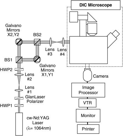
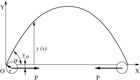
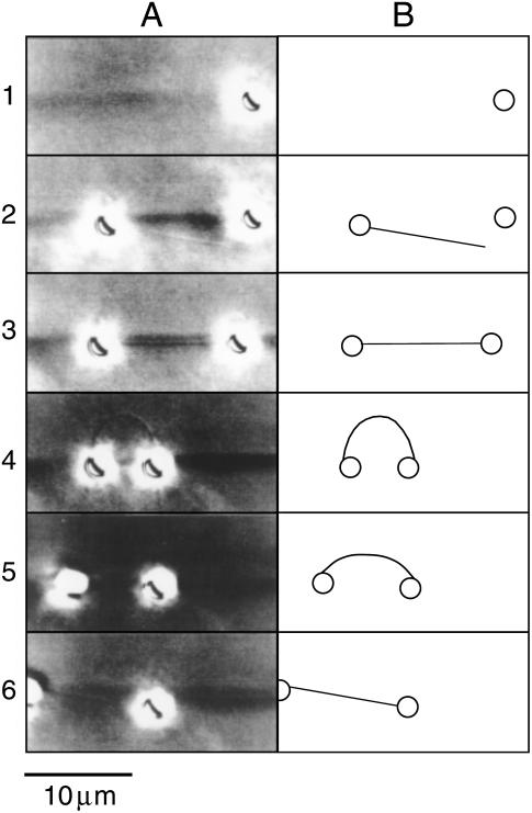
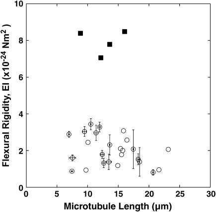
We used direct buckling force measurements with optical traps to determine the flexural rigidity of individual microtubules bound to polystyrene beads. To optimize the accuracy of the measurement, we used two optical traps and antibody-coated beads to manipulate each microtubule. We then applied a new analytical model assuming nonaxial buckling. Paclitaxel-stabilized microtubules were polymerized from purified tubulin, and the average microtubule rigidity was calculated as 2.0 x 10(-24) Nm2 using this novel microtubule buckling system. This value was not dependent on microtubule length. We also measured the rigidity of paclitaxel-free microtubules, and obtained the value of 7.9 x 10(-24) Nm2, which is nearly four times that measured for paclitaxel-stabilized microtubules.


Figures

FIGURE 1
FIGURE 1
Four types of methods for a single microtubule rigidity measurement. F is the microtubule internal spring force caused by deformation and P is the synthetic external force working on a microtubule.
FIGURE 2
FIGURE 2
Schematic diagram of the video-enhanced DIC microscope with optical traps. The laser power was controlled by rotating the half-wave plate, HWP1, followed by a Glan-Laser polarizer. The ratio of the two beams was changed by rotating the half-wave plate, HWP2. Two laser beams were independently manipulated by changing the angles of the galvano mirrors X1, Y1 and X2, Y2.
FIGURE 3
FIGURE 3
Schematic representation of a buckled microtubule. The X axis is chosen to pass through two fulcrums that represent attachment points of beads to a microtubule. The origin, O, is located at one of the fulcrums. The two polystyrene beads of radius r illustrate the nonaxial buckling case.
FIGURE 4
FIGURE 4
A typical example of single-microtubule capturing, buckling, and release with micromanipulation of antibody-coated beads and optical traps. (A) Video-printed images of the procedure for a paclitaxel-stabilized microtubule. The single microtubule can be seen faintly (the dark shadow of bead images makes it difficult to observe the microtubule). DIC images were used to observe the single microtubule, and thus the beads appear larger than their actual size due to halation. The background darkness of each image is slightly altered because the light source fluctuated slightly and contrast was strongly enhanced. (B) The trace of the images in A. Circles and lines represent beads and microtubules, respectively. Row 1 shows the first bead being captured with the right (stronger) optical trap. Row 2 shows the second bead with a single microtubule being captured with the left (weaker) trap. The microtubule on the bead could be observed by relative flow upon moving the stage. Row 3 shows the dumbbell-shaped image resulting from a single microtubule and beads. Row 4 shows just the buckling state of the microtubule upon moving the right bead toward the left. The left bead also moved fractionally to the left due to the buckling force. An additional short microtubule, which was not relevant to the analysis, can be seen on the right bead. Row 5 shows the left bead escaping from the trap and the buckling microtubule relaxing back to its straight form. The microtubule cannot be observed. Row 6 shows the final state in which the right bead is held by the trap and the bent microtubule straightens by its own elasticity. The left bead is free from the optical trap but remained bound to the microtubule. The right bead moved slightly toward the left in response to the release from the buckling force.
FIGURE 5
FIGURE 5
The plot of flexural rigidity of a single microtubule against microtubule length. Paclitaxel-stabilized microtubules (open circles) were buckled 1–5 times and 48 measurements of 25 microtubules were performed in total. The average and standard deviations for individual microtubules measured repeatedly are shown as a marker and error bars, respectively. Note that there was no length dependency of the flexural rigidity. For paclitaxel-free microtubules (solid squares), only four measurements of four microtubules were done. The average rigidity of paclitaxel-free microtubules (7.9 × 10⁻²⁴ Nm2) was approximately four-times-higher than that of paclitaxel-stabilized microtubules (2.0 × 10⁻²⁴ Nm2).

References

    1. Howard, J. 2001. Mechanics of Motor Proteins and the Cytoskeleton. Sinauer Associates, Sunderland, MA.
    1. Mizushima-Sugano, J., T. Maeda, and T. Miki-Noumura. 1983. Flexural rigidity of singlet microtubules estimated from statistical analysis of their contour lengths and end-to-end distances. Biochim. Biophys. Acta. 755:257–262. - PubMed
    1. Kurachi, M., M. Hoshi, and H. Tashiro. 1995. Buckling of a single microtubule by optical trapping force: direct measurement of microtubule rigidity. Cell Motil. Cytoskeleton. 30:221–228. - PubMed
    1. Tran, P. T., S. F. Parsons, R. Sterba, Z. Wang, M. P. Sheetz, and E. D. Salmon. 1995. Direct measurement of microtubule flexural rigidity with the laser trap. Mol. Biol. Cell. 6:260a.
    1. Felgner, H., R. Frank, and M. Schliwa. 1996. Flexural rigidity of microtubules measured with the use of optical tweezers. J. Cell Sci. 109:509–516. - PubMed

LinkOut - more resources