. 2005 Dec 27;102(52):18878-83.
doi: 10.1073/pnas.0509269102. Epub 2005 Dec 19.

Structure of the mid-region of tropomyosin: bending and binding sites for actin

Affiliations

Structure of the mid-region of tropomyosin: bending and binding sites for actin

Jerry H Brown et al. Proc Natl Acad Sci U S A. .

Abstract

Tropomyosin is a two-chain alpha-helical coiled coil whose periodic interactions with the F-actin helix are critical for thin filament stabilization and the regulation of muscle contraction. Here we deduce the mechanical and chemical basis of these interactions from the 2.3-A-resolution crystal structure of the middle three of tropomyosin's seven periods. Geometrically specific bends of the coiled coil, produced by clusters of core alanines, and variable bends about gaps in the core, produced by isolated alanines, occur along the molecule. The crystal packing is notable in signifying that the functionally important fifth period includes an especially favorable protein-binding site, comprising an unusual apolar patch on the surface together with surrounding charged residues. Based on these and other results, we have constructed a specific model of the thin filament, with the N-terminal halves of each period (i.e., the so-called "alpha zones") of tropomyosin axially aligned with subdomain 3 of each monomer in F-actin.


Figures
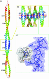
Fig. 1.
Fig. 1.
Coiled-coil temperature (B) factor and crystal contacts. (a) The most ordered (blue) region of the molecule occurs between residues 167 and 178 (boxed), which forms multiple close crystal contacts (see b and c). A long region with relatively high B factors (yellow and red) occurs in the N-terminal region of the fragment, where there is non-close packing between the helices in the coiled coil, centered at core alanines 120 and 134 (see Fig. 2). The helices at a cluster of three core alanines in a row (at blue triangle) are relatively well ordered and are axially staggered (see Figs. 3 and 6). (b and c) The most concentrated set of contacts between symmetry-related molecules occurs along the crystallographic 65 axis, involving residues 167–178. This 12-residue-long stretch of the 144-residue-long MidTm–GCN4 structure contains 30% of its close (<3.5 Å) crystal contacts (see Table 3, which is published as supporting information on the PNAS web site). (b) Four coiled coils in the unit cell are shown. Consecutive coiled-coil axes are related by the 60° rotation of the 65 axis (the left-most and right-most coiled coils here are related by a net 180°). Within a coiled coil, the two helical axes are related by an ≈20° crossing angle, so that the main crystal contacts are between nearly perpendicularly oriented helices. (c) These crystallographically related helices “embrace” each other using hydrophobic interactions surrounded by electrostatic contacts (see Results).
Fig. 2.
Fig. 2.
Isolated core alanines create holes in the coiled coil. Shown is a series of space-filling models of consecutive stretches of the structure, each one viewing the broad face of the coiled coil. The region from residue 141 to the C terminus of the fragment is well packed [average gap volume = 30 Å3 per residue pair (see Table 4, which is published as supporting information on the PNAS web site)] whereas that from residues 113–141 contains significant holes in the core (average gap volume = 67 Å3 per residue pair). The quality of the packing between the helices of the coiled coil relates to the sequential pattern of the sizes of the side chains at the interface between the helices (see Results and letters in Fig. 3).
Fig. 3.
Fig. 3.
Specific bends from alanine staggers at low coiled-coil radii, and holes and variable bends from isolated core alanines at high radii. The graph shown is the coiled-coil radius at the location of each residue of MidTm. The letters on the graph are the one-letter code of the local core side chain; the printed size of the letter correlates with the mass of the side chain, and the color of the graph indicates whether the α-helices have a local axial stagger greater than (blue) or less than (red) 1.0 Å. The cartoons depict different bends in the coiled coil (see Results); α-helices are depicted by straight or curved rectangles, and their coiling around one another is not shown for clarity. See also Fig. 6 and ref. .
Fig. 4.
Fig. 4.
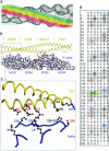
Model for the interaction between actin and tropomyosin. (a) The azimuthal positions of tropomyosin, in the off (red), Ca2+-activated (yellow) and fully activated (green) states, on F-actin (gray, adapted from ref. 56) according to electron microscopic studies (see text). The four subdomains of actin are labeled. (b) Proposed axial model of the thin filament in the Ca2+-activated state aligns the α zones of tropomyosin (yellow, current structure) over subdomain 3 (and subdomain 1) of F-actin (coordinates courtesy of K. C. Holmes, ref. and see text). [Note that, in this alignment, each period of tropomyosin (α zone followed by β zone) spans the actin–actin junction; one complete tropomyosin molecule (data not shown) would span six complete consecutive actin monomers and half of each of two others along the F-actin long-pitch helix.] The view shown is obtained by rotating panel A 90° about the horizontal axis and projecting an 18-Å-thick slab of the model at the Ca2+-activated azimuthal position. The N terminus of tropomyosin and the pointed end of actin are toward the right. The radial distance between the axes of tropomyosin and F-actin in this model is ≈38.5 Å, in agreement with experimentally determined values (e.g., ref. 57). (c) A close-up view of tropomyosin α zone 5 and actin showing the chemical basis for this model. The axial and rotational alignments are based on positioning apolar (black numbering), as well as oppositely charged (red, acid; blue, base), clusters of residues across from one another (see text). (d) Sequence of rat striated α-tropomyosin, emphasizing the outer surface (b, c, and f) residues from the α zones (shaded) that are proposed to form close contacts with subdomain 3 (and subdomain 1) of actin. Such acidic residues (red circles) are found in the C-terminal half of each of the seven α zones; a positive charged residue (blue square) followed by apolar residues (black diamonds) are found in the N-terminal half of most of tropomyosin's α zones. These outer surface apolar patches are most prominent in period 1 and period 5, with functionally critical (see text) period 5 having four apolar residues in a row in its sequence (green rectangle).

Similar articles

Cited by

References

    1. Crick, F. H. C. (1953) Acta Crystallogr. 6, 689–697.
    1. Cohen, C. & Parry, D. A. D. (1990) Proteins Struct. Funct. Genet. 7, 1–15. - PubMed
    1. O'Shea, E. K., Klemm, J. D., Kim, P. S. & Alber, T. (1991) Science 254, 539–544. - PubMed
    1. McLachlan, A. D. & Stewart, M. (1976) J. Mol. Biol. 103, 271–298. - PubMed
    1. Phillips, G. N., Fillers, J. P. & Cohen, C. (1986) J. Mol. Biol. 192, 111–131. - PubMed

Publication types

Associated data

LinkOut - more resources