

Minimizing clip artifacts in multi CT angiography of clipped patients
- PMID: 16418357
- PMCID: PMC7976073
Minimizing clip artifacts in multi CT angiography of clipped patients
Abstract
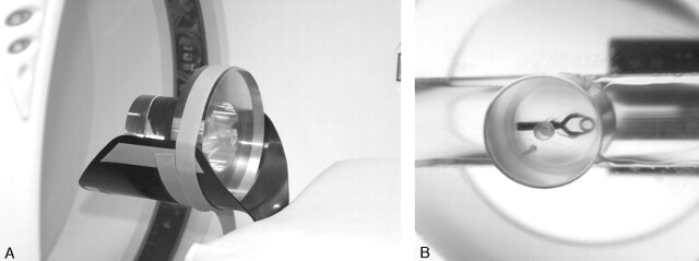
Purpose: To optimize the multi CTA (MSCTA) protocol, the influence of pitch, kilovoltage peak (kVp), reconstruction algorithm, type, and orientation of the clip on clip-induced artifacts was investigated in a phantom study. Also, the influence of kVp, concentration of contrast material, and clip orientation in clipped patients was studied.
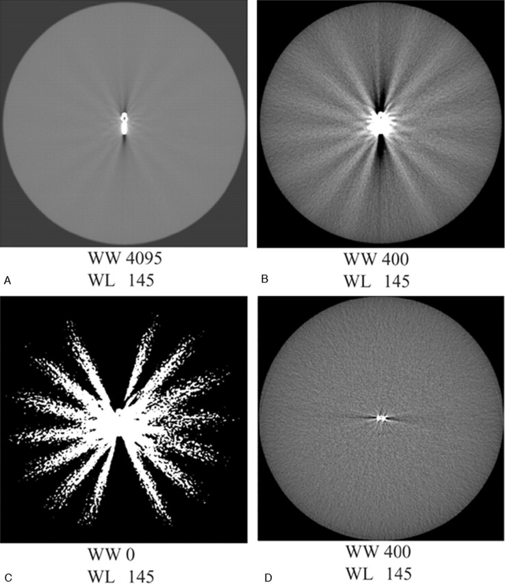
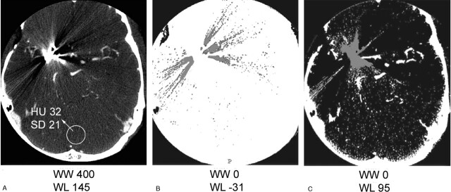
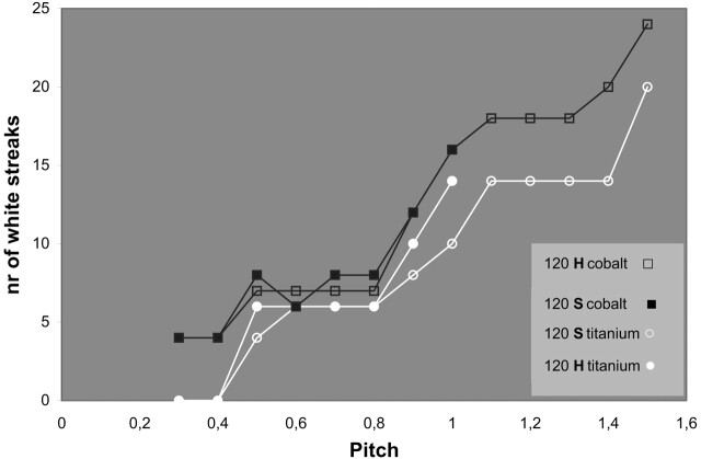
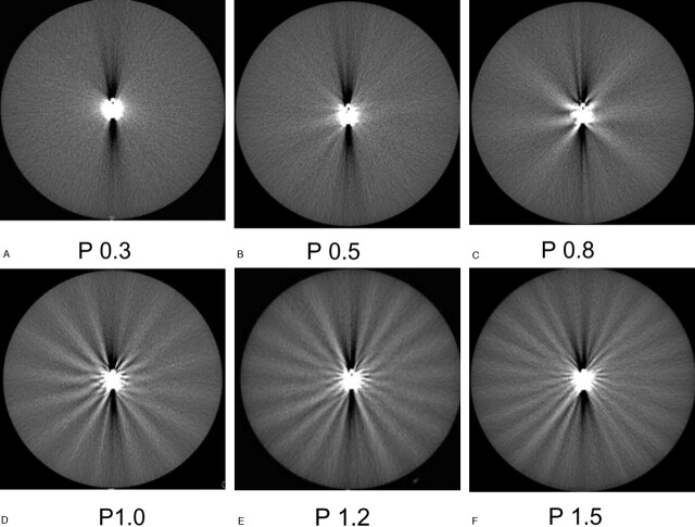
Methods: A phantom containing a clip was scanned with varying parameters. Artifact was quantified with 3D volumetry. Artifact volumes were compared for the different parameters. In addition, the number of artifact streaks was presented as a function of the pitch. Five clipped patients were scanned with 90 kVp and 120 kVp and 5 with 120 kVp and 140 kVp. The artifact area was compared. The visualization at the clip site was evaluated for different clip orientations in 50 patients, and for 140 kVp with 370 mg iodine/mL contrast (I/mL) compared with 120 kVp/300 mg I/mL in 7 patients.
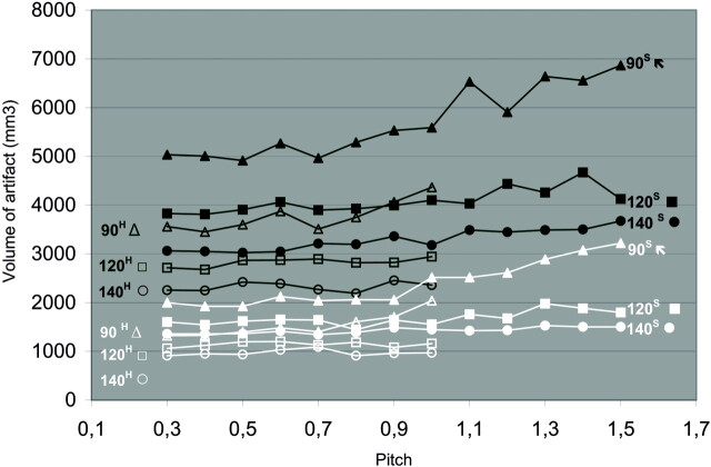
Results: Up to a pitch of 0.6, there was hardly an increase in artifact. Higher kVp and linear interpolation resulted in fewer artifacts. Alloy clips containing cobalt produced more artifact than did titanium clips. Clips positioned perpendicular to the scan plane led to significantly less artifact. In patients with clips, scanning with 140 kVp/370 mgI/mL led to a decrease of artifact area and a better visualization of the clip site. The visualization at the clip site was also better for clips perpendicular to the scan plane.
Conclusions: If clip artifacts are to be minimized, we suggest scanning with a pitch of 0.6, by using 140 kVp and 370 mgI/mL contrast.
Figures
References
-
- van Gijn J, Rinkel GJ. Subarachnoid haemorrhage: diagnosis, causes and management. Brain 2001;124:249–78 - PubMed
-
- Thornton J, Debrun GM, Aletich VA, et al. What percentage of surgically clipped intracranial aneurysms have residual necks? Neurosurgery 2000;46:1294–98 - PubMed
-
- Lin T, Fox AJ, Drake CG. Regrowth of aneurysm sacs from residual neck following aneurysm clipping. J Neurosurg 1989;70:556–60 - PubMed
-
- Tsutsumi K, Ueki K, Usui M, et al. Risk of subarachnoid hemorrhage after surgical treatment of unruptured cerebral aneurysms. Stroke 1999;30:1181–84 - PubMed
-
- Tsutsumi K, Ueki K, Morita A, et al. Risk of aneurysm recurrence in patients with clipped cerebral aneurysms: results of long-term follow-up angiography. Stroke 2001;32:1191–94 - PubMed
MeSH terms
Substances
LinkOut - more resources
Full Text Sources
Other Literature Sources
Medical