. 2006 Feb 8;25(3):457-66.
doi: 10.1038/sj.emboj.7600959. Epub 2006 Jan 19.

A rivet model for channel formation by aerolysin-like pore-forming toxins

Affiliations

A rivet model for channel formation by aerolysin-like pore-forming toxins

Ioan Iacovache et al. EMBO J. .

Abstract

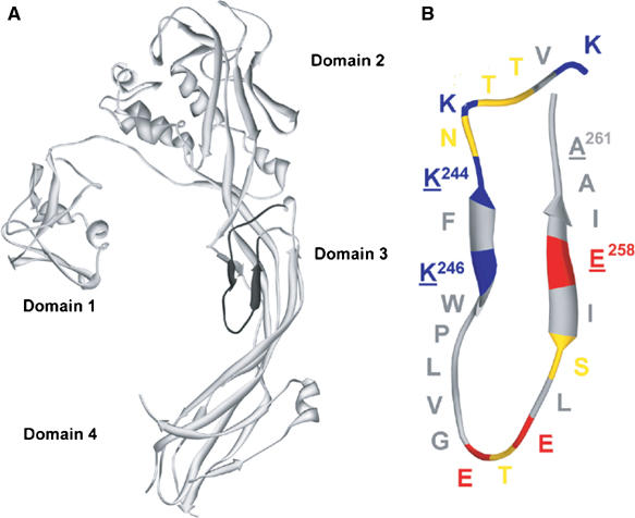
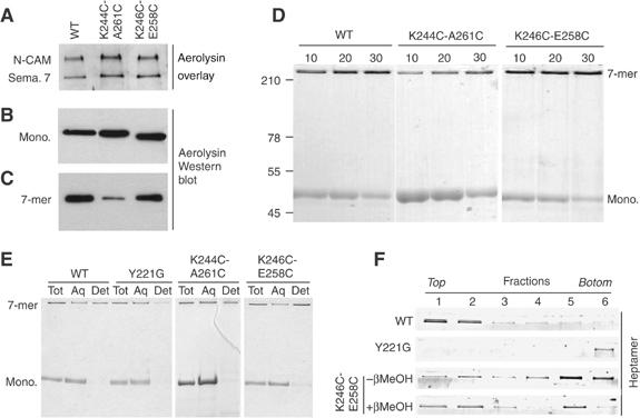
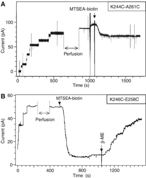
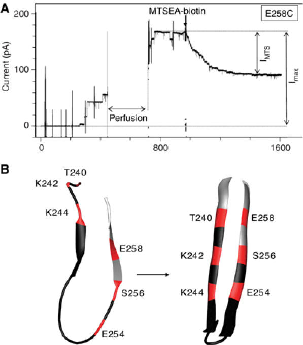
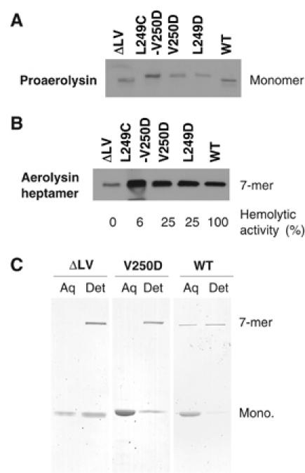
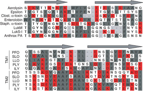
The bacterial toxin aerolysin kills cells by forming heptameric channels, of unknown structure, in the plasma membrane. Using disulfide trapping and cysteine scanning mutagenesis coupled to thiol-specific labeling on lipid bilayers, we identify a loop that lines the channel. This loop has an alternating pattern of charged and uncharged residues, suggesting that the transmembrane region has a beta-barrel configuration, as observed for Staphylococcal alpha-toxin. Surprisingly, we found that the turn of the beta-hairpin is composed of a stretch of five hydrophobic residues. We show that this hydrophobic turn drives membrane insertion of the developing channel and propose that, once the lipid bilayer has been crossed, it folds back parallel to the plane of the membrane in a rivet-like fashion. This rivet-like conformation was modeled and sequence alignments suggest that such channel riveting may operate for many other pore-forming toxins.


Figures

Figure 1
Figure 1
Proaerolysin structure. (A) Ribbon diagram of the proaerolysin X-ray structure (Parker et al, 1994). The DIII-loop in domain 3 (residues K238–A261) is indicated in black. (B) Schematic representation of the DIII-loop. Acidic residues are shown in red, basic residues in blue, polar uncharged residues in yellow and hydrophobic residues in gray. The alternating pattern of charged/uncharged (hydrophobic) residues is broken by a patch of five consecutive hydrophobic residues (W247–G251). Underlined residues represent residues mutated in the K244C-A261C and K246C-E258C double cysteine mutants. Figures were generated using DeepView (Guex and Peitsch, 1997) and rendered using Pov-Ray (http://www.povray.org/).
Figure 2
Figure 2
Receptor binding, heptamerization and membrane association of the disulfide-containing mutants. (A) The disulfide-containing mutants were tested in an aerolysin overlay assay on BHK cell extracts (40 μg protein per lane). Aerolysin was revealed using anti-aerolysin antibodies followed by an HRP-labeled secondary antibody. Binding to two GPI-anchored proteins, N-CAM and semaphorin 7 (sema. 7), is illustrated. (B) BHK cells were incubated with trypsin-activated WT or disulfide-containing mutant aerolysins (400 ng/ml) at 4°C for 1 h. Cell extracts (40 μg per lane), from which the nuclei were cleared by centrifugation, were analyzed by Western blotting using an anti-toxin antibody. (C) BHK cells, treated with trypsin-activated WT or mutant aerolysin as in panel B, were washed and further incubated at 37°C for 45 min. The presence of heptamers was revealed by Western blotting against aerolysin. (D) The ability of the disulfide-containing mutants to oligomerize in vitro was assayed by monitoring the appearance of the heptamer as a function of time after trypsin activation. SDS gels were revealed by Coomassie blue staining. (E) WT, Y221G and disulfide-containing mutant proaerolysins were activated with trypsin and allowed to heptamerize in vitro and then submitted to a Triton X-114 partitioning assay. Aliquots from the total sample (Tot), the aqueous (Aq) and detergent (Det) phases were analyzed by SDS–PAGE and Coomassie blue staining. (F) WT, Y221G, K246C-E258C and reduced K246C-E258C heptamer were reconstituted into proteoliposomes and submitted to separation by sucrose density flotation gradients. The six fractions of the gradient, from top to bottom, were analyzed by SDS–PAGE and Coomassie blue staining.
Figure 3
Figure 3
Channel analysis of the disulfide-containing mutants. The K244C-A261C (A) and K246C-E258C (B) mutants were incubated with βMeOH, activated with trypsin and added to the cis chamber of the bilayer setup, after having generated an EggPC:DOPE (1:1) membrane between the two chambers. After 5–10 channels had formed, the cis chamber was perfused as indicated. At the time indicated by an arrow, MTSEA-X-biotin was added to the trans chamber at 200 nM. For both K244C-A261C (A) and K246C-E258C (B), a decrease in current was observed, an effect that could be reversed by the addition of βMeOH as shown for K246C-E258C mutant (B).
Figure 4
Figure 4
Effect of MTSEA labeling on the single cysteine mutants. (A) The E258C single cysteine mutant was incubated with βMeOH and activated with trypsin and added to the cis chamber of the bilayer setup. After formation of some channels, free toxin was removed by perfusion of the cis chamber, as indicated. At the time indicated by an arrow, MTSEA-X-biotin was added to the trans chamber at 200 nM. (B) Schematic diagram illustrating the positions in the DIII-loop where cysteine residues were sensitive to thiol labeling (red) or insensitive (black). On the left panel, the loop is shown with the conformation it has in the crystal structure of the proaerolysin dimer (Parker et al, 1994). On the right panel, the loop is shown in the β-hairpin configuration as modeled in the current work (see Figure 6A and B).
Figure 5
Figure 5
Mutagenesis of the hairpin LV tip does not prevent aerolysin binding and heptamerization. WT or mutant (L249D, V250D, L249C-V250D and DLV) proaerolyins were incubated for 10 min at room temperature with erythrocyte ghosts and analyzed by Western blotting with anti-PA antibodies (A). (B) Following proaerolysin binding, erythrocytes were treated with trypsin for 10 min at room temperature to convert proaerolysin to aerolysin, and then with a 10-fold excess of trypsin inhibitor. Oligomerization was allowed to proceed for 60 min and samples were analyzed by Western blotting against the toxin. (C) WT and mutants were activated with trypsin for 20 min at room temperature followed by addition of trypsin inhibitor, and allowed to oligomerize for 60 min. Samples were submitted to Triton X-114 partitioning. Aqueous (Aq) and detergent (Det) phases were analyzed by SDS–PAGE and Coomassie blue staining.
Figure 6
Figure 6
The rivet model of the transmembrane aerolysin β-barrel. Our model of the aerolysin transmembrane β-barrel is shown as a ribbon diagram from the side (A). One of the β-hairpins is highlighted in dark gray and the side chains are shown as balls and sticks. The membrane is shown as a semitransparent gray box. The rivet model as seen from the top (B) with the channel lining residues space-filled. Acidic residues are shown in red, basic residues in blue, polar uncharged residues in yellow and hydrophobic residues in gray. In this rivet model, the tip of each loop folds back, with the hydrophobic residues pointing up toward the core of the bilayer and the flanking charged residues snorkeling down toward the polar head groups. (C) Ribbon diagram of a side view of the Staphylococcal transmembrane β-barrel (Song et al, 1996). One of the β-hairpins is highlighted in dark gray and the side chains are shown as balls and sticks. (D) Space-filled model of the Staphylococcal transmembrane β-barrel (the cap and rim domains were omitted) viewed from the top, that is, the side where the cap domain is located. (E) Ribbon diagram of the β-barrel of the bacterial outer membrane iron transporter FhuA (Ferguson et al, 1998; Locher et al, 1998) (PDB code: 1BY3). The plug domain was omitted for clarity. Side chains for hairpins 9 and 10 are shown as balls and sticks using the same color code as in panel A. The hairpins 9 and 10 of FhuA were extracted from the structure to better illustrate side-chain conformations (F). Similar types of loops were found in osmoporin (Dutzler et al, 1999) (1OSM) (G) and in maltoporin loop (Meyer et al, 1997) (2MPR) (H).
Figure 7
Figure 7
Alignments of putative transmembrane domains of different β-barrel PFT. The DIII-loop of aerolysin was aligned manually with the corresponding regions in C. perfringens epsilon-toxin (a toxin with a similar three-dimensional structure to aerolysin) (Cole et al, 2004), Clostridial α-toxin (Clost. α-toxin) and enterolobin, three Staphylococcal PFT (α-toxin, LukM, LukS-I) and the protective antigen (PA) of anthrax (Nassi et al, 2002) as well as the two transmembrane domains (TM1 and TM2) of five cholesterol-dependent cytolysins (PFO: perfringolysin; SLO: streptolysin; LLO: listeriolysin; PLY: pneumolysin; ILY: intermedilysin; Tweten et al, 2001). Alignments were generated based on the alternating pattern of polar and hydrophobic residues. Hydrophobic residues are shown in gray, charged residues in red and other residues are left uncolored.

Similar articles

Cited by

References

    1. Abrami L, Fivaz M, Glauser P-E, Parton RG, van der Goot FG (1998) A pore-forming toxin interact with a GPI-anchored protein and causes vacuolation of the endoplasmic reticulum. J Cell Biol 140: 525–540 - PMC - PubMed
    1. Abrami L, Fivaz M, van Der Goot FG (2000) Adventures of a pore-forming toxin at the target cell surface. Trends Microbiol 8: 168–172 - PubMed
    1. Abrami L, van der Goot FG (1999) Plasma membrane microdomains act as concentration platforms to facilitate intoxication by aerolysin. J Cell Biol 147: 175–184 - PMC - PubMed
    1. Ballard J, Crabtree J, Roe BA, Tweten RK (1995) The primary structure of Clostridium septicum alpha-toxin exhibits similarity with that of Aeromonas hydrophila aerolysin. Infect Immun 63: 340–344 - PMC - PubMed
    1. Bordier C (1981) Phase separation of integral membrane proteins in Triton X-114 solution. J Biol Chem 256: 1604–1607 - PubMed

Publication types

LinkOut - more resources