

Real-time MRI guided atrial septal puncture and balloon septostomy in swine
- PMID: 16532499
- PMCID: PMC1463249
- DOI: 10.1002/ccd.20579
Real-time MRI guided atrial septal puncture and balloon septostomy in swine
Abstract
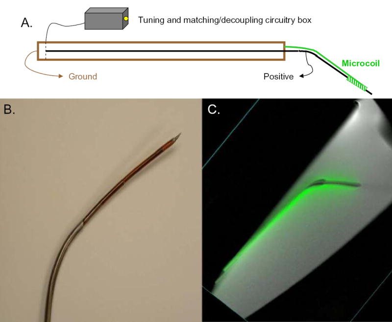
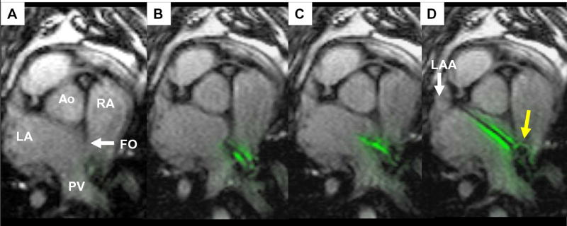
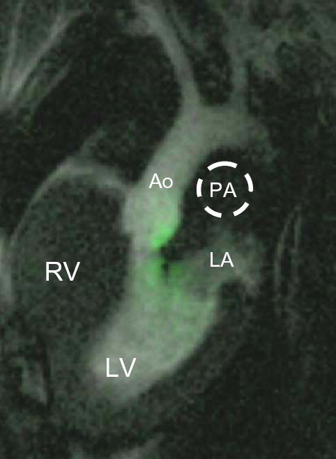
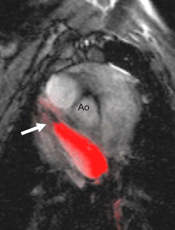
Cardiac perforation during atrial septal puncture (ASP) might be avoided by improved image guidance. X-ray fluoroscopy (XRF), which guides ASP, visualizes tissue poorly and does not convey depth information. Ultrasound is limited by device shadows and constrained imaging windows. Alternatively, real-time MRI (rtMRI) provides excellent tissue contrast in any orientation and may enable ASP and balloon atrial septostomy (BAS) in swine. Custom MRI catheters incorporated "active" (receiver antenna) and "passive" (iron or gadolinium) elements. Wholly rtMRI-guided transfemoral ASP and BAS were performed in 10 swine in a 1.5T interventional suite. Hemodynamic results were measured with catheters and velocity encoded MRI. Successful ASP was performed in all 10 animals. Necropsy confirmed septostomy confined within the fossa ovalis in all. BAS was successful in 9/10 animals. Antenna failure in a re-used needle led to inadvertent vena cava tear prior to BAS in 1 animal. ASP in the same animal was easily performed using a new needle. rtMRI illustrated clear device-tissue-lumen relationships in multiple orientations, and facilitated simple ASP and BAS. The mean procedure time was 19 +/- 10 minutes. Septostomy achieved a mean left to right shunt ratio of 1.3:1 in these healthy animals. Interactive rtMRI permits rapid transcatheter ASP and BAS in swine. Further technical development may enable novel applications.
Figures
Similar articles
-
Real-time magnetic resonance imaging-guided endovascular recanalization of chronic total arterial occlusion in a swine model.Circulation. 2006 Feb 28;113(8):1101-7. doi: 10.1161/CIRCULATIONAHA.105.586727. Epub 2006 Feb 20. Circulation. 2006. PMID: 16490819 Free PMC article.
-
Magnetic resonance image-guided trans-septal puncture in a swine heart.J Magn Reson Imaging. 2005 Apr;21(4):463-7. doi: 10.1002/jmri.20262. J Magn Reson Imaging. 2005. PMID: 15779027
-
[Efficacy of fenestrated atrial septal defect occulders on pulmonary hypertension dogs].Zhonghua Xin Xue Guan Bing Za Zhi. 2022 Feb 24;50(2):166-171. doi: 10.3760/cma.j.cn112148-20220102-00002. Zhonghua Xin Xue Guan Bing Za Zhi. 2022. PMID: 35172462 Chinese.
-
Use of Balloon Atrial Septostomy in Patients With Advanced Pulmonary Arterial Hypertension: A Systematic Review and Meta-Analysis.Chest. 2019 Jul;156(1):53-63. doi: 10.1016/j.chest.2019.03.003. Epub 2019 Mar 23. Chest. 2019. PMID: 30910639 Free PMC article.
-
Intervention in the critically ill neonate and infant with hypoplastic left heart syndrome and intact atrial septum.J Interv Cardiol. 2001 Jun;14(3):357-66. doi: 10.1111/j.1540-8183.2001.tb00345.x. J Interv Cardiol. 2001. PMID: 12053397 Review.
Cited by
-
The Future of Paediatric Heart Interventions: Where Will We Be in 2030?Curr Cardiol Rep. 2020 Oct 9;22(12):158. doi: 10.1007/s11886-020-01404-z. Curr Cardiol Rep. 2020. PMID: 33037461 Free PMC article. Review.
-
Experimental validation of robot-assisted cardiovascular catheterization: model-based versus model-free control.Int J Comput Assist Radiol Surg. 2018 Jun;13(6):797-804. doi: 10.1007/s11548-018-1757-z. Epub 2018 Apr 2. Int J Comput Assist Radiol Surg. 2018. PMID: 29611096
-
Real-time magnetic resonance imaging-guided endovascular recanalization of chronic total arterial occlusion in a swine model.Circulation. 2006 Feb 28;113(8):1101-7. doi: 10.1161/CIRCULATIONAHA.105.586727. Epub 2006 Feb 20. Circulation. 2006. PMID: 16490819 Free PMC article.
-
MR fluoroscopy in vascular and cardiac interventions (review).Int J Cardiovasc Imaging. 2012 Jan;28(1):117-37. doi: 10.1007/s10554-010-9774-1. Epub 2011 Feb 26. Int J Cardiovasc Imaging. 2012. PMID: 21359519 Free PMC article. Review.
-
Interventional cardiac magnetic resonance imaging: current applications, technology readiness level, and future perspectives.Ther Adv Cardiovasc Dis. 2022 Jan-Dec;16:17539447221119624. doi: 10.1177/17539447221119624. Ther Adv Cardiovasc Dis. 2022. PMID: 36039865 Free PMC article.
References
-
- Cope C. Technique for transseptal catheterization of the left atrium; preliminary report. J Thorac Surg. 1959;37(4):482–6. - PubMed
-
- Ross J, Jr, Braunwald E, Morrow AG. Transseptal left atrial puncture; new technique for the measurement of left atrial pressure in man. Am J Cardiol. 1959;3(5):653–5. - PubMed
-
- Mullins CE. Transseptal left heart catheterization: experience with a new technique in 520 pediatric and adult patients. Pediatr Cardiol. 1983;4(3):239–45. - PubMed
-
- Braunwald E. Cooperative study on cardiac catheterization. Transseptal left heart catheterization. Circulation. 1968. pp. III74–9. - PubMed
-
- Friedrich SP, Berman AD, Baim DS, Diver DJ. Myocardial perforation in the cardiac catheterization laboratory: incidence, presentation, diagnosis, and management. Cathet Cardiovasc Diagn. 1994;32(2):99–107. - PubMed
MeSH terms
Grants and funding
LinkOut - more resources
Full Text Sources
Medical
