. 2006 Sep;15(9):1326-38.
doi: 10.1007/s00586-006-0103-2. Epub 2006 Apr 8.

Anterior retropharyngeal fixation C1-2 for stabilization of atlantoaxial instabilities: study of feasibility, technical description and preliminary results

Affiliations

Anterior retropharyngeal fixation C1-2 for stabilization of atlantoaxial instabilities: study of feasibility, technical description and preliminary results

Heiko Koller et al. Eur Spine J. 2006 Sep.

Abstract

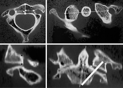
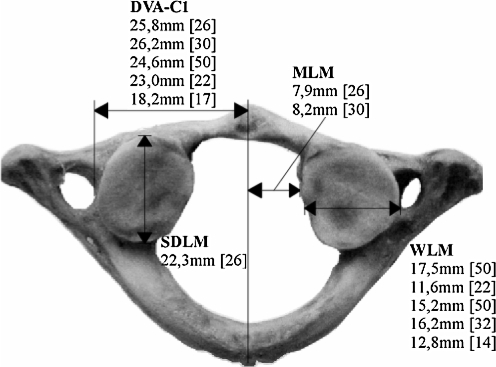
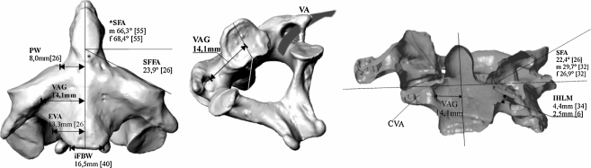
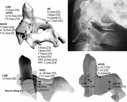
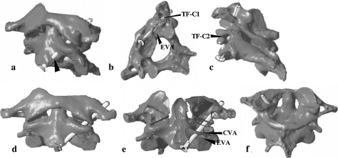
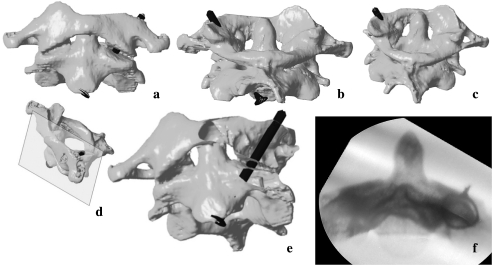
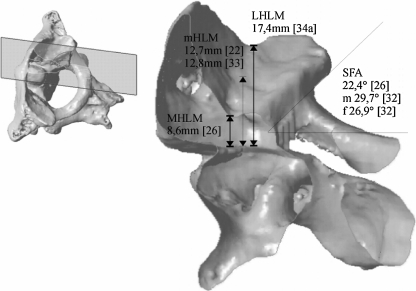
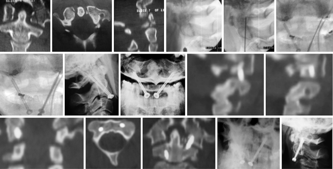
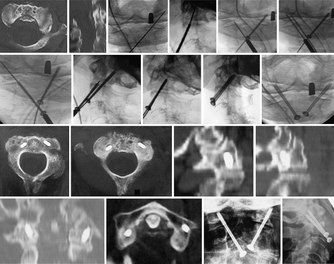
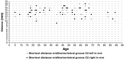
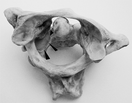
Posterior transarticular screw fixation C1-2 with the Magerl technique is a challenging procedure for stabilization of atlantoaxial instabilities. Although its high primary stability favoured it to sublaminar wire-based techniques, the close merging of the vertebral artery (VA) and its violation during screw passage inside the axis emphasizes its potential risk. Also, posterior approach to the upper cervical spine produces extensive, as well as traumatic soft-tissue stripping. In comparison, anterior transarticular screw fixation C1-2 is an atraumatic technique, but has been neglected in the literature, even though promising results are published and lectured to date. In 2004, anterior screw fixation C1-2 was introduced in our department for the treatment of atlantoaxial instabilities. As it showed convincing results, its general anatomic feasibility was worked up. The distance between mid-sagittal line of C2 and medial border of the VA groove resembles the most important anatomic landmark in anterior transarticular screw fixation C1-2. Therefore, CT based measurements on 42 healthy specimens without pathology of the cervical spine were performed. Our data are compiled in an extended collection of anatomic landmarks relevant for anterior transarticular screw fixation C1-2. Based on anatomic findings, the technique and its feasibility in daily clinical work is depicted and discussed on our preliminary results in seven patients.


Figures

Fig. 1
Fig. 1
In preoperative atlantoaxial CT scans, relevant distances for ATS are measured. Upper left Vertebral body depth and distance between VAG and mid-sagittal-line C2. Upper right Distance between transverse foramen C1 and mid-sagittal-line C1-2. Lower left Medial height of lateral mass C1. Lower right Width between mid-sagittal-line C2 and medial offset of superior facet C2 including the ‘real’ pedicle C2, possible screw inclination and width of lateral mass C1
Fig. 2
Fig. 2
Morphometric parameters for screw placement inside C1. DVA-C1 distance vertebral artery groove C1 to mid-sagittal-line C1, SDLM sagittal depth of lateral mass C1, WLM width of lateral mass C1, MLM distance between mid-sagittal-line C1 and lateral mass C1
Fig. 3
Fig. 3
Morphometric parameters concerning course of the VA and screw placement inside C1-2. VAG distance between mid-sagittal-line C2 and vertebral artery groove C2—own results, EVA distance between entry point of vertebral artery to mid-sagittal-line C2, SFFA superior frontal facet angle C2, SFA superior facet angle C1 and C2, iFBW inferior frontal body width, PW width between mid-sagittal-line C2 and medial offset of superior facet C2 including the ‘real’ pedicle C2, IHLM internal height of lateral mass, m/f data separated for male and female specimen
Fig. 4
Fig. 4
Morphometric parameters concerning screw placement in ATS and PTS. Upper right The Harris-Ring-C2 and its upper posterior bow resembles the posterior threshold to be passed by a screw in ATS. LBD lateral body depth; APSD anterior–posterior sagittal diameter of axis body; DSFD diagonal surface diameter of lateral mass; IH height of Isthmus C2; IW width of Isthmus C2; PI-VAG distance from pars interarticularis to posterior border of VAG; IHLM internal height of lateral mass C2; SSFL superior sagittal facet lenght; m/f data separated for male and female specimen
Fig. 5
Fig. 5
Pitfalls in ATS. ad Too far lateral screw placement endangers the VA and increases risk of screw cut-out. b, e The osseous canal of the VA inside the lateral mass C2 can be harmed, if screw angulation is too steep. f A too far medialized screw can cause breaching of the atlantooccipital joint. TF-C1 transverse foramen C1, TF-C2 transverse foramen C2, CVA osseous canal of vertebral artery, EVA entry point of vertebral artery
Fig. 6
Fig. 6
Ideal screw placement in ATS (oversized screw lengths shown). a, b Screw entry point is to be chosen at the pinafore C2 for the first and a bit posteriorly underneath the pinafore C2 for the second screw to prevent screw cut-out anteriorly. c The screws should direct to the lateral rim of the lateral mass C1. d Image depicts plane of view in (e). e Ideal screw placement inside C1-2. f A cerclage wire surrounding the Isthmus C2 with the X-ray beam in direction to its angulation: the medial cortical border of Isthmus C2 resembles a possible lateral threshold for screw angulation
Fig. 7
Fig. 7
Morphometric parameters concerning screw placement inside the lateral mass C1. It resembles a cupped fossa and its medial height strongly differs from its lateral counterpart. Therefore, the length of screw taps should respect preoperative measurements. mHLM middle height of lateral mass C1, MHLM medial height of lateral mass C1, LHLM lateral height of lateral mass C1, SFA superior facet angle C1
Fig. 8
Fig. 8
Case 1: unstable Jefferson’s fracture. After control of rotation C1-2, first and second k-wire placement underneath the pinafore C2, screw placement was performed. Postoperative CT scans showed favourable alignment C1-2 with solid screw purchase. One year after ATS, there was a fracture union and still solid screw purchase with stable atlantoaxial joints
Fig. 9
Fig. 9
Case 4: unstable odontoid fracture with partially ankylosed atlantodental joint. Stiff neck did not enable k-wire and screw placement underneath pinafore C2. First k-wire placement is on the right too far medial. Correct k-wire placement is on the left. As there was correct rotation C1-2, the third k-wire was passed parallel to the first right-sided one. It guided to the lateral rim of the right lateral mass C1. Finally, solid screw purchase inside C1-2 was achieved. Operation time was 42 min. As suggested in final X-rays, there was some breaching of the right atlantooccipital joint without any clinical consequences. After 5 months, follow-up demonstrated solid screw anchorage, stable atlantoaxial joints, and a pain-free clinical result
Graph 1
Graph 1
Template showing age-related distances between mid-sagittal-line C2 and medial border of VAG in 42 patients. There was no trend towards decreased distances in young or elderly patients
Fig. 10
Fig. 10
Prior to k-wire and screw placement in ATS, malrotation C1-2 is to be excluded. Otherwise, misplacement of the screws with instability will result

Similar articles

Cited by

References

    1. {'text': '', 'ref_index': 1, 'ids': [{'type': 'PubMed', 'value': '9202272', 'is_inner': True, 'url': 'https://pubmed.ncbi.nlm.nih.gov/9202272/'}]}
    2. Apostolides PJ, Theodore N, Karahalios DG, Sonntag VK (1997) Triple anterior screw fixation of an acute combination atlas-axis fracture. J Neurosurg 87:96–99 - PubMed
    1. {'text': '', 'ref_index': 1, 'ids': [{'type': 'DOI', 'value': '10.1007/s00113-003-0701-y', 'is_inner': False, 'url': 'https://doi.org/10.1007/s00113-003-0701-y'}, {'type': 'PubMed', 'value': '14999380', 'is_inner': True, 'url': 'https://pubmed.ncbi.nlm.nih.gov/14999380/'}]}
    2. Bading S, Pape HC, Lange U, Bastian L, Krettek C (2004) Reosteosynthesis in dens pseudarthrosis. Case report and review of the literature (in german). Unfallch 107:149–153 - PubMed
    1. None
    2. Barbour JR (1971) Screw fixation in fractures of the odontoid process. S Aust Clinics 5:20
    1. {'text': '', 'ref_index': 1, 'ids': [{'type': 'DOI', 'value': '10.1007/s00064-006-0035-3', 'is_inner': False, 'url': 'https://doi.org/10.1007/s00064-006-0035-3'}, {'type': 'PubMed', 'value': '17008962', 'is_inner': True, 'url': 'https://pubmed.ncbi.nlm.nih.gov/17008962/'}]}
    2. Blauth M, Dienst M, Schmidt U, Krettek C (1997) Instrumentarium zur perkutanen Verschraubung C1/C2. Oper Orthop Traum 9:242–248 - PubMed
    1. None
    2. Bremerich FH, Dvorak J, Mannion AF, Grob D (2003) Long-term results after posterior transarticular C1–C2 fusion lecture. CSRS-E, Barcelona, Spain

Publication types

MeSH terms