

In vitro studies of the neuroform microstent using transparent human intracranial arteries
Affiliations
- PMID: 16687559
- PMCID: PMC7975717
Item in Clipboard
In vitro studies of the neuroform microstent using transparent human intracranial arteries
AJNR Am J Neuroradiol.
2006 May.
Abstract
For better understanding of relevant morphology and mechanics, direct visualization of a Neuroform microstent (NFM) within an actual human intracranial artery is essential. Twelve NFM were deployed into 8 various segments of formaldehyde-fixed cadaver intracranial arteries. The arteries were then dehydrated and cleared in methyl salicylate to create transparency. The morphology of NFM was studied by digital macro-photography with a back illumination system. The possible limitations and important findings of the NFM were discussed.
Figures
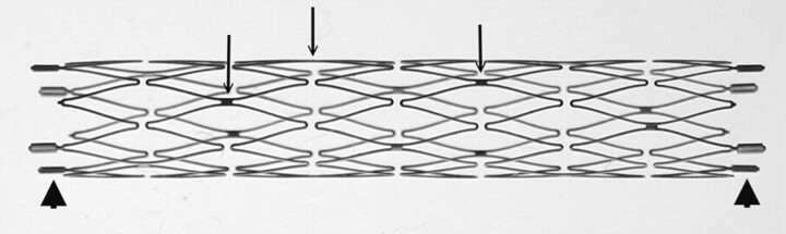
Macro-digital photography of an expanded 3.5 × 20 mm Neuroform2 microstent. Only the platinum markers at the bilateral ends are radiopaque (arrowheads). The struts (arrows; do not indicate all struts) are connecting the crown segments. Each segment has 2 struts with approximately 180° in orientation and 90° difference in between adjacent struts.
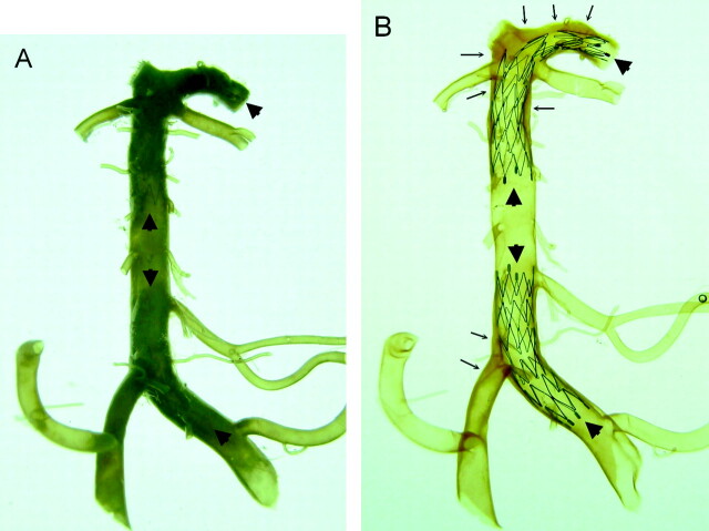
Comparison of a vertebrobasilar artery with its major branches and proximal posterior cerebral arteries before (A) and after (B) the artery was made transparent. Two Neuroform microstents are in position (arrowheads). One stent is across the left vertebral and basilar artery and another is located across the distal basilar artery and posterior cerebral artery. The stents are clearly visualized through the artery after arteries are made transparent (B). Using this method, assessment of the mechanical behaviors of Neuroform microstent in actual human intracranial arteries is possible. Extensive atherosclerotic plaques (arrows) are noted in this specimen that involve the right vertebrobasilar junction, the distal basilar artery, and the bilateral posterior cerebral arteries.
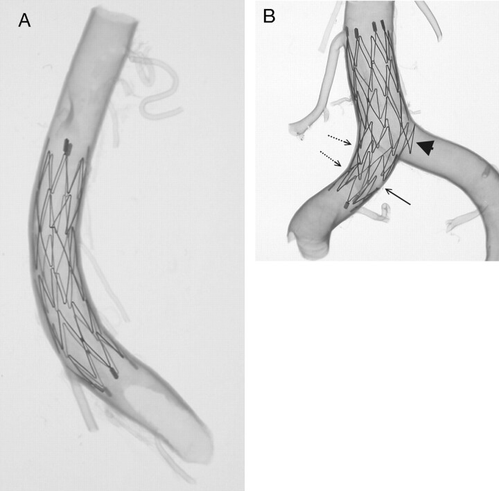
A 4.5 × 15-mm Neuroform microstent in a transparent basilar trunk (A) and another 4.5 × 15-mm Neuroform microstent across another transparent vertebrobasilar junction (B). Overall, the Neuroform microstents show very good conformity to the vessel wall. Increasing curvature may cause focal intercrown separation (diminished scaffolding) along the greater curvature of an artery (arrow). Conversely, along the lesser curvature of an arterial segment, there is a tendency for crowns to imbricate (dot-line arrows). Part of the crown of the stent protrudes into the major side branch, which is mimicking the neck of an aneurysm (arrowhead).
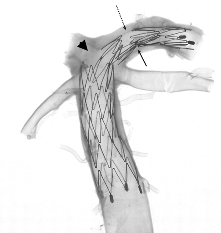
Magnified view of the upper stent (Neuroform2 microstent with the size of 3.5 × 20 mm) shown in Fig 2. The stent placed in the basilar artery to left posterior cerebral artery (PCA) continuum with angulated configuration shows a significant gap in the stent just at the bifurcation of the right PCA (arrowhead), which barely covers the opening of the right PCA. The connecting struts rotated to within less than the ideal 180° orientation (arrow), resulting in a very large and asymmetric intersegmental gap at the opposite end (dot-line arrow) of the stent.
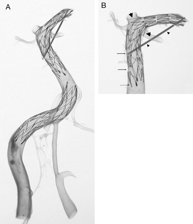
Two Neuroform2 microstents (3.5 × 20 mm) are shown in a transparent vertebrobasilar system (A). One stent is located at the right vertebral artery (VA) to the proximal basilar artery (BA) continuum. The other stent is located at the basilar trunk to the left posterior cerebral artery (PCA) continuum. Hypoplasia of the left VA and a large atherosclerotic plaque in right VA are noted. Magnified view of the upper stent in BA-PCA continuum (B) shows a similar finding in Fig 3B where part of the crown segment protrudes into major side branches, the left PCA, and left superior cerebellar artery (large arrowheads). Asymmetric cell enlargement of the stent was seen in which gaps between crown segments developed in the straight segment of the BA (arrows). This was probably a consequence of pulling the delivery catheter too fast compared with the rate of pushing on the constrained stent. This also caused poor wall attachment of the proximal end of the stent (dot-line arrow) at the straight segment of the BA, which is generally very uncommon. A thin sheath is fixed to maintain the BA-PCA angle before deploying the stent in the artery (small arrowheads) because of the longitudinal rebounding force, which may straighten the natural angulation of the BA-PCA continuum.
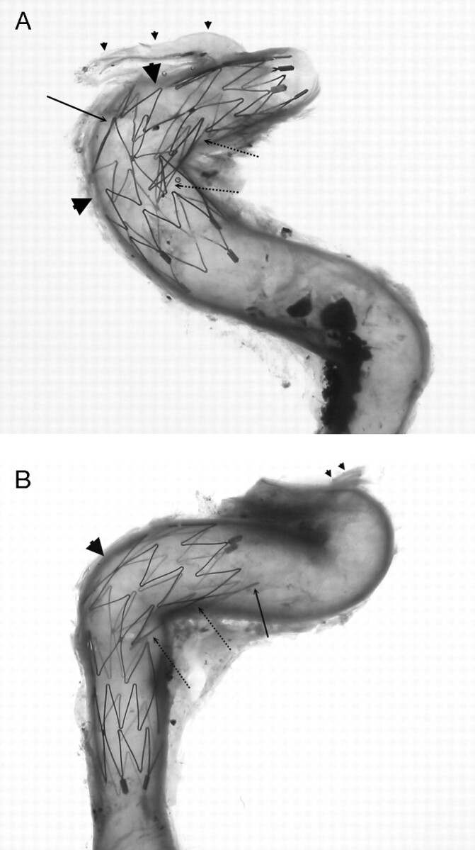
Neuroform microstents (4.5 × 15 mm) placed in cavernous (A) and petrous (B) segments of the internal carotid artery crossing the angulations of the vessels. Significant large gaps are observed in the greater curvature of the vessels (arrowheads), except that one connecting strut is in place (arrow in A). If this connecting strut were located at the actual neck of an aneurysm, the stent would have a good bridge for coiling. On the other hand, the crown segments of the stent are consistently not well attached to the arterial wall along the lesser curvature of the vessels (dot-line arrows). The end of the stent is also not always attached well to the vessel wall especially at arterial curves (arrow in B). Ophthalmic arteries are indicated (small arrowheads).
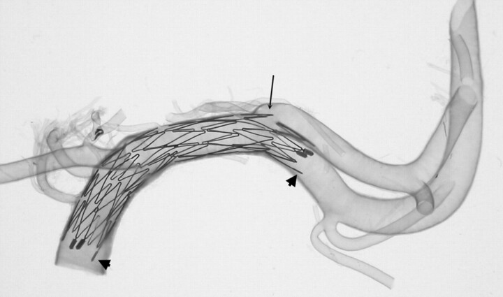
A 3.5 × 20-mm Neuroform2 microstent deployed from the terminal end of the internal carotid artery to the middle cerebral artery. A small part of the crown segment protrudes into the M2 bifurcation (arrow). The end of the stent is not attached to the artery very well, particularly at arterial curves (arrowheads). This finding is relatively common in other specimens.
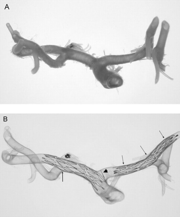
An intracranial arterial segment of the internal carotid artery, middle cerebral artery (MCA), and anterior cerebral artery (ACA) continuum showing its original configuration (A) and the final transparency appearance after the Neuroform microstent deployment (B). The stents were deployed in the MCA (including part of the distal ICA, 4.5 × 15 mm) and the ACA (3.5 × 20 mm), respectively. A connecting strut is observed at the origin of the M1 bifurcation (arrow), which shows a very smooth profile for the stent at the interface of the parental artery and major side branch. Conversely, the protrusion of part of another crown of the stent is seen at the origin of the ACA (arrowhead). Straightening of the ACA complex (A1–A2) indicates the longitudinal rebounding force of the stent present when the stent is bent (dot-line arrows).
References
-
- Howington JU, Hanel RA, Harrigan MR, et al. The Neuroform stent, the first microcatheter-delivered stent for use in the intracranial circulation. Neurosurgery 2004;54:2–5 - PubMed
-
- Karino T, Motomiya M. Flow visualization in isolated transparent natural blood vessels. Biorheology 1983;20:119–27 - PubMed
-
- Lylyk P, Cohen JE, Ceratto R, et al. Endovascular reconstruction of intracranial arteries by stent placement and combined techniques. J Neurosurg 2002;97:1306–13 - PubMed
Publication types
MeSH terms
LinkOut - more resources
Full Text Sources
Other Literature Sources